


G-7
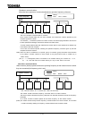
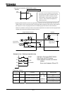
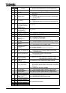
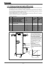
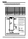
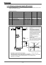
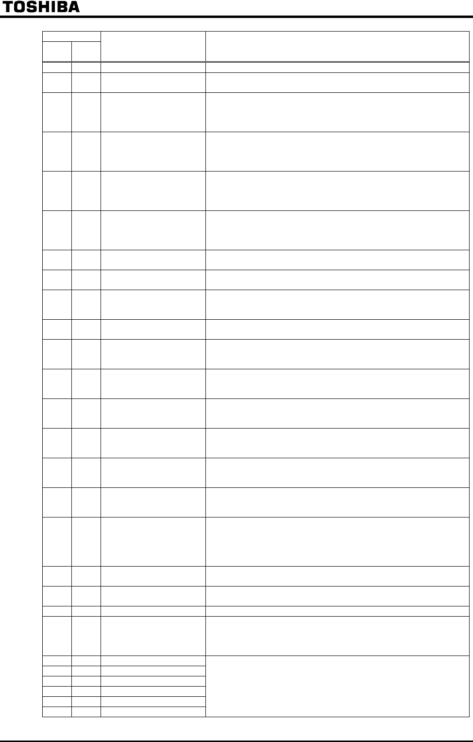
Parameter setting
Positive
logic
Negative
logic
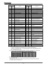
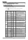
Function Operation output specifications (in case of positive logic)
38 39 PID deviation limit "ON": PID deviation is in or set value.
40 41 Run/stop
"ON": Running frequency is output or DC injection breaking ()
is performed.
42 43 Serious failure
"ON": Serious failure(refer to technical terms on the previous page)
is detected.
"OFF": Inverter has recovered from serious failure. (Serious failure
has been reset)
44 45 Light failure
"ON": Light failure (refer to technical terms on the previous page) is
detected.
"OFF": Inverter has recovered from light failure. (Light failure has
been reset)
46 47
Commercial/INV
switching output #1
(for inverter operation
output)
Refer to 6.16.
48 49
Commercial/INV
switching output #2
(for commercial
operation output)
Refer to 6.16.
50 51 Cooling fan ON/OFF
"ON": Cooling fan is in operation.
"OFF": Cooling fan is off operation.
52 53 In Jog run
"ON": In jog run.
"OFF": In normal operation.
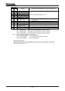
54 55
Panel operation/terminal
board operation
switching
"ON": In operation by terminal board.
"OFF": In operation by control panel.
56 57
Cumulative operation
time alarm
"ON": Cumulative operation time is beyond the set value.
"OFF": Cumulative operation time is less than the set value.
58 59
Abnormal communication
alarm #1
(caused by scanning)
"ON": Communication error caused by scanning has occurred.
"OFF": Communication error is cancelled (reset).
60 61
Forward/reverse
switching
"OFF": In forward operation.
"ON": In reverse operation.
(The last status is held while operation is suspended.)
62 63 Ready for operation #1
"ON": In operable status or operation can be started with frequency
command input as an operation switching answer-back.
"OFF": In inoperable status.
64 65 Ready for operation #2
"ON": In operable status or operation can be started with ST and
RUN signals and frequency command input
"OFF": In inoperable status.
66 67
Poor control power supply
() pre-alarm
"ON": Control circuit under-voltage is detected ().
(detection level; 200V class: approx. 145 VAC or lower,
400V class: approx. 290 VAC or lower)
68 69
System consistent
sequence
(BR: Brake release)
Output the braking signal according to the brake sequence.
70 71 In (pre-)alarm status
"ON": More than one of alarm, pre-alarm, under-voltage, low
current over-torque, poor control power supply, PID deviation
limit, abnormal frequency setting or torque limit have occurred
or detected.
"OFF": All the alarms above are cancelled.
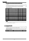
72 73
Forward speed limit
(torque control)
"ON": Forward operation speed is set value or over.
"OFF": Forward operation speed is less than set value.
74 75
Reverse speed limit
(torque control)
"ON": Reverse operation speed is set value or over.
"OFF": Reverse operation speed is less than set value.
76 77 Inverter healthy output "ON" and "OFF" are alternately output at intervals of 1 second.
78 79
Abnormal communication
alarm #2 (caused by
RS485 logic or
message transmission)
"ON": Communication error caused by RS485 logic or message
transmission has occurred.
"OFF": Communication error is cancelled (reset).
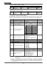
80 81 Error code output #1
82 83 Error code output #2
84 85 Error code output #3
86 87 Error code output #4
88 89 Error code output #5
90 91 Error code output #6
Output the failure code in 6bits.