


L-3
(Continued from the preceding page)
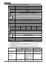
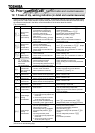
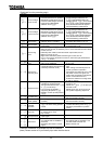
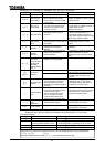
Indication
Contents Expected causes
Countermeasures
(*1)
Under-voltage
(main circuit)
Input voltage (main circuit)
becomes insufficient in operation.
Momentary power failure occurs
because undervoltage continues
longer than under-voltage
detection time .
Check input voltage.
If undervoltage is detected, set
(regenerative power ride-
through control), (auto-restart)
and (under-voltage detection
time) as countermeasures against
future momentary power failure.
(*1)
Under-voltage
(control circuit)
Input voltage (control circuit)
becomes insufficient in operation.
Momentary power failure occurs
because undervoltage continues
longer than under-voltage
detection time .
Check input voltage.
If undervoltage is detected, set
(regenerative power ride-
through control), (auto-restart)
and (under-voltage detection
time) as countermeasures against
future momentary power failure.
(*1)
Over-torque
Load torque reaches over-torque
detection level in operation.
Check the system if there is
something abnormal in it or not.
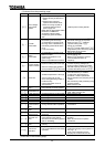
Ground-fault
Output cable or motor falls into
ground-fault.
Check units and connections if there
is ground-fault or not.
Auto-tuning
error
Check settings of to parameters for motor.
Motor whose capacity is smaller by two or more ranks than that of inverter
is used, isn't it?
Extremely think cable is used as inverter output cable, isn't it?
Motor is running, isn't it?
Motor other than three-phase inductive type is used, isn't it?
If error occurs as power is turned on, set motor type parameter as
= (others).
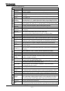
Inverter type
error
Is control board (or drive board of
main circuit) replaced?
When board has been replaced, input
for .
Sink/source
switching error
Sink/source switch of
input/output terminal is set wrong
(reversely switched on/off).
Check connections and set proper
logic.
After making sure that sequence is
normal, proceed in operation.
If the same error does not occur when
the power is turned on again, the
system has recovered normal status.
(Check control terminals and
sink/source switches including those
of add-on options.)
Sequence error
The signal from a system is not
inputted into input terminals.
The input terminal function (
or ) is not set up.
For not using the system-
supporting sequence
function, it is set up except 0.0 at
.
Please check if the sequence is
normal or not.
Please set or as the input
terminal to use.
Please set up 0.0, when you do not
use system-supporting sequence.
Encoder error
Disconnection of encoder circuit. Check connection of encoder.
Connect encoder correctly.
Speed error
(Over speed)
Something abnormal in encoder
(inverter)
Check connection of encoder.
Connect encoder correctly.
To much
potential
deviation
Potential deviation exceeded the
set value during position
control.
Check connection of encoder.
Increase the setting value of .
Adjust the parameters on position
control
Key error
RUN or STOP key is depressed
for 5 seconds or more.
Key is faulty.
Check operation panel.
VI/II input error
Breaking down of a wire for VI/II
input signal.
Check VI/II input signal
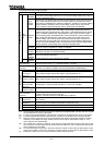
Read-error
Connection between the inverter
and optional add-on cassettes is
abnormal.
Something abnormal in control
signal.
Check connection between the inverter
and optional add-on cassettes. If it is
not reset, make a service call.
Make a service call.
Presence or absence of parameter trip can be selected.
(Note) Please contact us if you find any trips other than the above.