


C-3
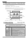
3.2 Simple operation of the VF-A7 [1] [Speed control mode]
A speed control mode can be selected from among three: control panel operation, terminal board
operation and combination of both. (Refer to 5.3 for other modes of operation.)
[Terminal operation] : Operation by means of external signals
[Panel operation] : Operation by means of keys on the control panel
[Panel + terminal operation] : Frequency, start and stop signals can be sent individually
from the control panel and the terminal board.
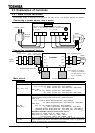
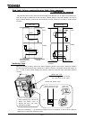
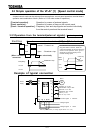
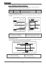
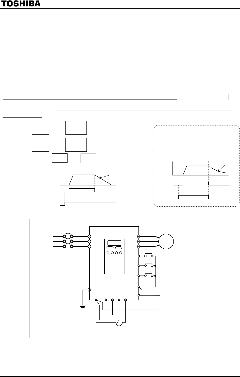
3.2.1Operation from the terminal(external signals) Terminal operation
Start/Stop Operation command mode selection [Default setting]
and closed : Forward run
and open : Slowdown stop
(When terminals and are electrically
connected.
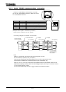
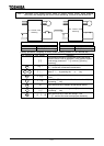
Example of typical connection
To make the motor coast to a stop (coast
stop),described on the left, break the
connection between ST and CC when the
motor is out of operation. Then, is
displayed on the LED display of the
inverter rotating speed,
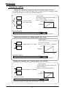
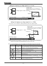
Frequency
Terminal
Termina
Motor
speed
F-CC
ST-CC
Coast stop
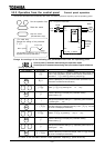
Motor
IM
G/E
CC RX
VI
RR PP
F
R
CC
R/L1
U/T1
Control panel
External potentiometer (or voltage signal RR-CC: 0 to 10V)
Voltage signal
Voltage signal 0 10Vdc
ST
V/T2
W/T3
S/L2
T/L3
Current signal 4 20mAdc
I I
Power
supply
Forward run if ON
Deceleration stop if OFF
Reverse run if ON,
Slowdown stop if OFF
Stand-by if ON,
free-run stop if OFF
Slowdown stop