


F-40
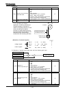
6.21 Torque control
Refer to 5.11 for switch to Torque control
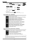
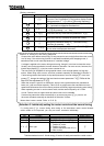
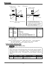
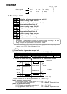
6.21.1 Torque reference
Torque reference selection
Torque reference mode selection
VI/II reference point #1 rate VI/II reference point #1
VI/II reference point #2 rate VI/II reference point #2
RR reference point #1 rate RR reference point #1
RR reference point #2 rate RR reference point #2
RX reference point #1 rate RX reference point #1
RX reference point #2 rate RX reference point #2
BIN reference point #1 rate BIN reference point #1
BIN reference point #2 rate BIN reference point #2
Panel torque reference (Refer to 6.29.11 for details.)
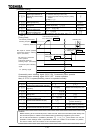
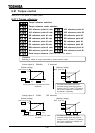
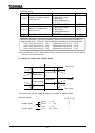
Current signal 4 20mAdc II terminal
[Default setting]
Torque produced: 0% at 4mAdc and 100%
at 20mAdc.
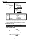
Voltage signal 0 10Vdc RR terminal
[Default setting]
Torque produced: 0% at 0Vdc and 100%
at 10Vdc.
Function
Selecting a mode of torque command in torque control mode.
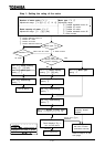
The relationship between the torque
command and the motor torque can be
changed. The and settings
0 and 100% correspond to currents of 0
and 20mAdc, respectively.
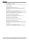
The relationship between the torque
command and the motor torque can be
changed. The and settings
0 and 100% correspond to voltages of 0
and 10Vdc, respectively.
[Arbitrary setting]
Motor torque [%]
0
[Arbitrary setting]
Motor torque [%]
20% 100%
0
100
4mA 20mA
Motor torque [%]
0
Motor torque [%]
0% 100%
0
100
0V 10V