F-68
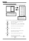
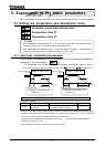
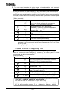
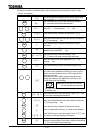
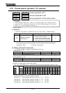
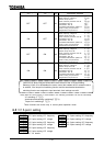
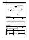
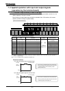
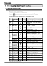
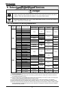
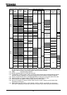
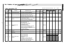
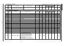
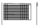
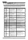
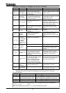
Title Function
Adjustment
range
Default
setting
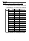
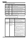
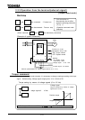
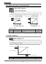
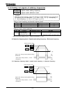
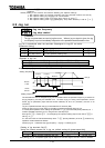
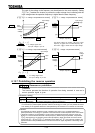
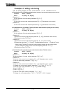
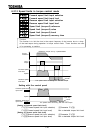
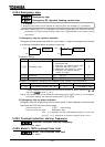
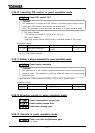
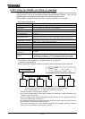
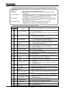
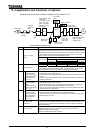
Value displayed after
change (example)
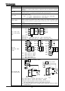
: 1 [s]
: 0.1 [s]
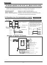
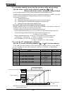
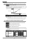
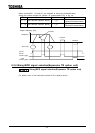
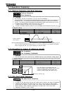
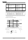
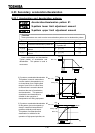
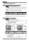
Decimal place number of
Acceleration/deceleration
time
: 0.01 [s]
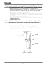
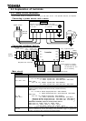
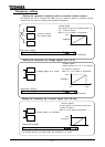
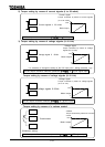
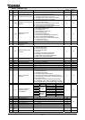
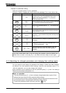
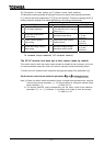
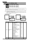
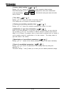
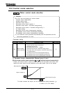
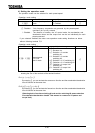
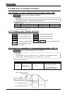
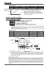
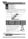
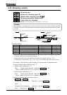
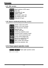
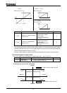
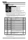
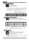
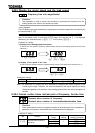
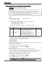
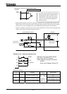
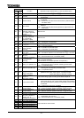
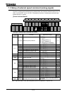
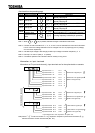
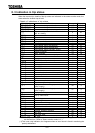
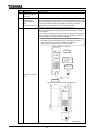
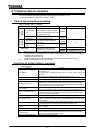
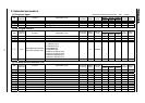
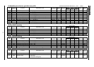
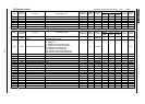
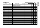
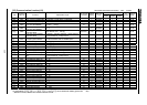
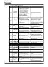
6.29.5 Changing items displayed in status monitor mode
Monitor display mode setting
Status monitor #1 display mode
Status monitor #2 display mode
Status monitor #3 display mode
Status monitor #4 display mode
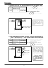
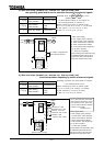
These parameters are used to select the item to be displayed when the power is turned on and
also to change items displayed in status monitor mode. Refer to 8.1 for details.
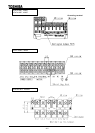
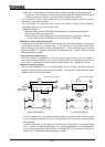
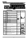
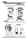
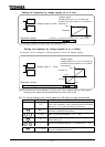
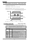
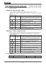
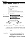
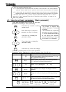
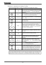
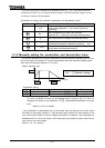
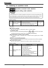
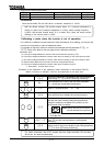
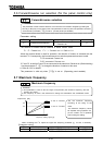
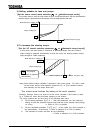
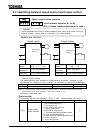
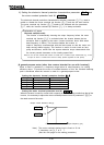
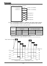
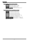
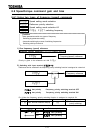
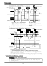
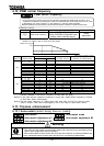
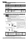
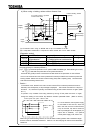
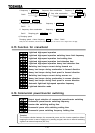
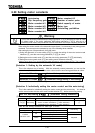
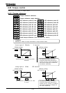
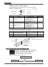
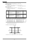
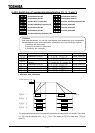
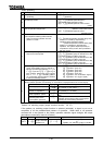
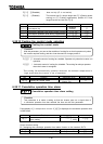
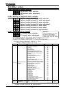
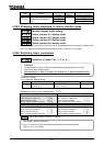
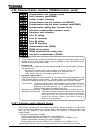
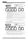
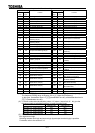
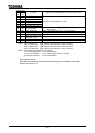
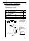
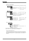
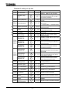
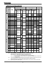
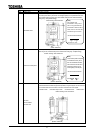
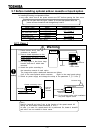
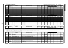
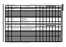
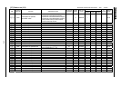
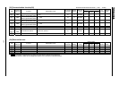
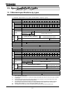
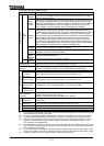
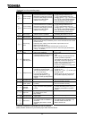
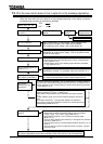
6.29.6 Switching basic parameters
Selection of panel V/f1, 2, 3 or 4
[Parameter setting]
V/f1 is selected default setting.
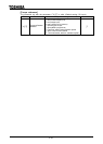
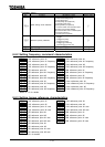
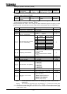
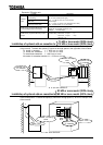
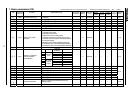
Title Function Adjustment range Default setting
Selection of panel
V/f1,2,3 or 4
1: V/f1, 2: V/f2,
3: V/f3, 4: V/f4
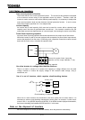
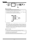
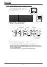
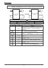
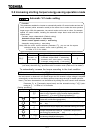
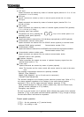
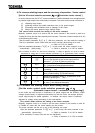
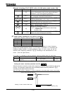
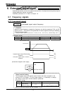
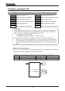
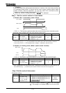
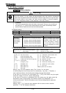
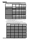
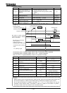
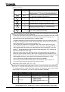
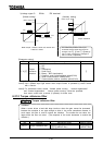
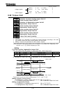
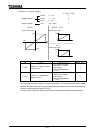
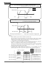
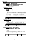
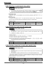
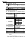
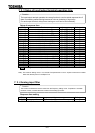
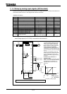
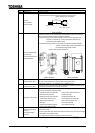
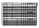
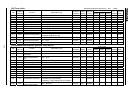
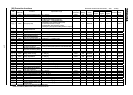
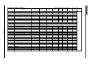
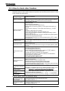
[Parameters which can be switched with ]
(V/f1) (V/f2)
Base frequency #1
Base frequency voltage #1
Manual torque boost
Motor overload protection level #1
Base frequency #2
Base frequency voltage #2
Manual torque boost #2
Motor overload protection level #2
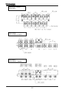
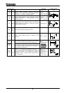
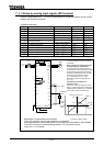
(V/f3) (V/f4)
Base frequency #3
Base frequency voltage #3
Manual torque boost #3
Motor overload protection level #3
Base frequency #4
Base frequency voltage #4
Manual torque boost #4
Motor overload protection level #4
: Parameter groups selected by default
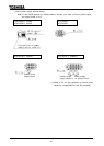
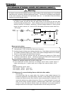
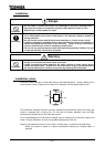
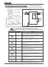
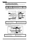
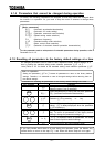
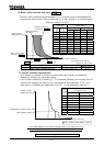
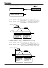
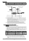
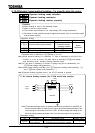
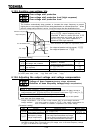
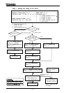
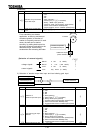
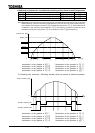
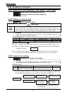
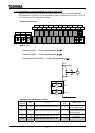
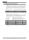
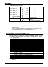
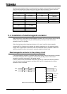
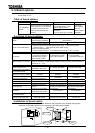
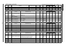
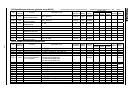
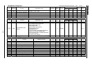
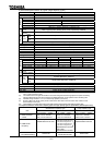
Function
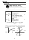
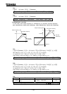
This parameter is used to switch V/f characteristics during operation or to drive
four motors with a single inverter.
This parameter is valid only when the inverter is in panel operation mode.
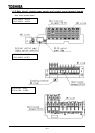
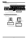
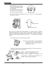
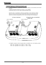
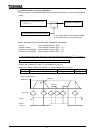
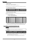
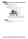
Switching by means of terminals
The V/f1, 2, 3 and 4 can also be switched by switching on and off terminals.
Refer to 6.4.1 for details.