


F-9
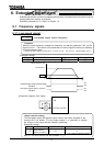
6.4 Basic parameters #2
6.4.1 Switching among V/f characteristics #1, #2, #3 and #4 from input terminal
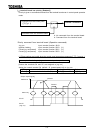
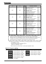
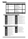
Base frequency #2 Manual torque boost #3
Base frequency voltage #2
Motor overload protection level #3
Manual torque boost #2 Base frequency #4
Motor overload protection level #2
Base frequency voltage #4
Base frequency #3 Manual torque boost #4
Base frequency voltage #3
Motor overload protection level #4
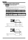
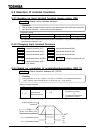
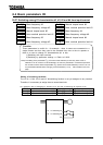
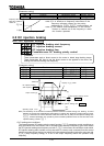
Setting of switching terminals
The V/f #1, V/f #2, V/f #3 and V/f #4 switching function is not yet assigned to any terminal.
Therefore, it is necessary to assign them to unused terminals.
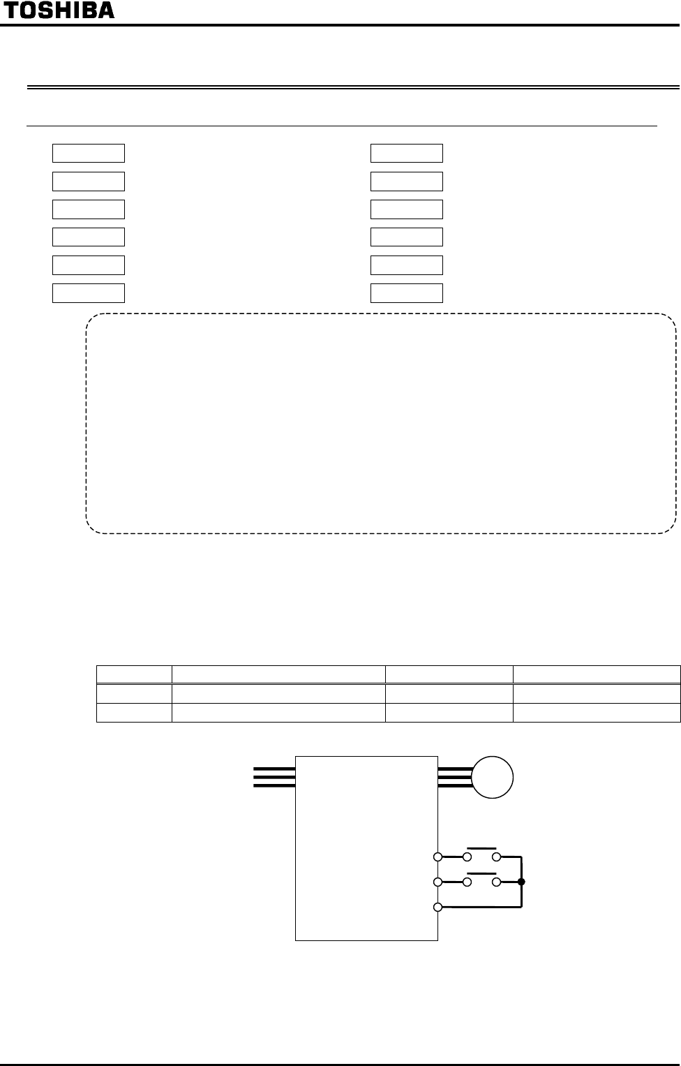
Ex.) Assigning the V/f switching #1 function to S1 and the V/f switching #2 function to S2.
Title Function Adjustment range Setting value
Input terminal selection #5(S1)
: (V/f switching #1)
Input terminal selection #6(S2)
: (V/f switching #2)
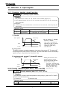
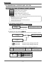
Function
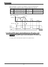
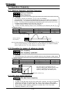
These parameters is useful for - for example - when 4 motors are connected to a
single inverter and thus they need to be switched from time to time to operate or
there is a need to change V/f characteristics (#1 to #4).
1) Switching with input terminal
2) Switching by parameter settings => Refer to 6.29.6.
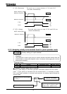
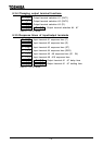
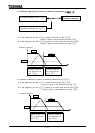
Note) The setting of the parameter (V/f control mode selection) is valid only when V/f #1 is
selected. If V/f #2, V/f #3 or V/f #4 is selected, V/f control is performed in constant torque mode.
Do not switch motors when the parameter (Motor control mode selection) is set at 7, 8 or 9.
For parameters selected when changing V/f characteristics (1 to 4), refer to table on the next
page.
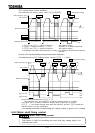
S1 V/f switching #1
S2 V/f switching #2
CC