


G-5
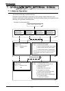
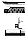
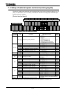
7. 2. 2 Functions of output terminals (in case of sink logic)
These functions are used to output various signals from the inverter to external equipment.
The functions from 0 through 119 can be utilized by setting parameters for the OUT1, OUT2, FL
(FLA, FLB, FLC) of the control terminal board.
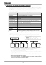
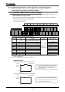
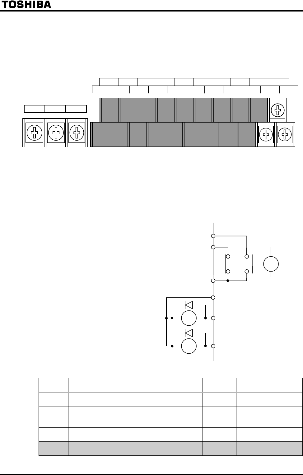
Control terminal board
How to use
Function of OUT1 To be set by parameter
Function of OUT2 To be set by parameter
Functions of FLA, FLB, FLC To be set by parameter
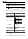
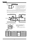
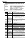
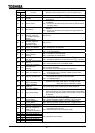
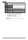
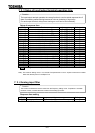
Setting of output terminal functions
Symbol of
terminal
Title Function
Adjustment
range
Default setting
OUT1 Output terminal selection #1(OUT1)
(Low speed signal)
OUT2 Output terminal selection #2(OUT2)
(Acceleration/decelera
tion completion)
FL Output terminal selection #3(FL)
(Failure FL)
Option
Output terminal selection #4 #7
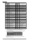
P24
OUT1
FLA
FLB
FLC
OUT2
Ry
Ry
FL