


E-25
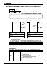
1) Setting the electronic thermal protection characteristics parameter and
the motor overload protection level #1
The electronic thermal protection characteristics selection parameter is used to
enable or disable the motor overload trip function () and the soft stall function.
The motor overload trip function () needs to be selected with the parameter
, while the inverter overload trip function () is always activated.
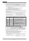
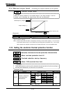
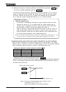
[A general-purpose motor (other than motors intended for use with inverters)]
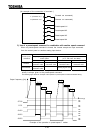
When a motor is operated in a frequency range below its rated frequency, its cooling
efficiency drops. To prevent the motor to overheat because of this, the overload detecting
point is advanced when the inverter is used for a general-purpose motor.
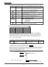
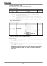
Setting the electronic thermal protective function
Set value Overload protection Overload stall
protect not stall
protect stall
not protect not stall
not protect stall
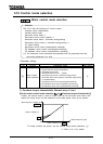
Setting the motor overload protection level #1
When the inverter is used for a motor with a capacity or a current rating smaller than that of the
inverter, it is necessary to adjust the motor overload protection level #1 parameter to
the rated current of the motor.
Explanation of terms
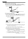
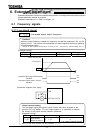
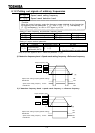
Overload stall(Soft stall):
The function of automatically lowering the output frequency before the motor
overload trip function is activated when the inverter detects that an
excessive load is applied to the motor. (Lowers maximum about 48Hz when
base frequency is 60Hz.) This function enables the inverter to
output a frequency commensurate with the load current so that the motor can
keep running without tripping. This function is useful for such loads as fans,
pump and blowers, which have the square reduction torque characteristic that
the current passed decreases as the rotating speed falls.
Note) Do not use this overload stall function for loads with a constant torque characteristic (e.g., a belt
conveyer to which a constant load current is always passed regardless of their speed).
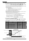
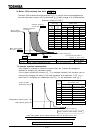
Note) The motor overload starting level is fixed at 30 Hz.
If necessary, set
at .
(See the next page for the setting procedure.)
0.6
1.0
Output frequency [Hz]
Output current reduction rate [%]
0
30