


J-20
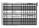
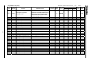
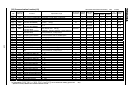
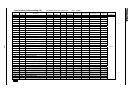
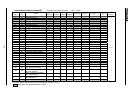
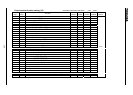
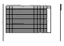
[33] Communication function(1/2)
Vector control
Title
Communi
cation No
Function Adjustment range
Min. unit (panel/
communication)
Default
setting
Write during
running
Speed
control
To rque
control
Position
control
V/f
Constant
Reference
section
0800
Communication rate (common serial)
0: 1200, 1: 2400, 2:4800, 3: 9600 3Enabled/ / / 6.30
0801
Parity (common serial/RS485)
0: No parity, 1: Even parity, 2: Odd parity 1Enabled/ / / 6.30
0802
Inverter number(common)(*1)
0 255 1/1 0 Enabled / / / 6.30
0803
Communication time-out
(common serial/RS485)
0: OFF, 1 100 [s] 1/1 0 Enabled / / / 6.30
0804
Communication time-out action
(common serial /RS485)
0 8 8Enabled/ / / 6.30
0805
Communication waiting time
(common serial)
0.00: Normal, 0.01 2.00 [s] 0.01/0.01 0.00 Enabled / / / 6.30
0806
Inter-drive communication
(common serial)
0: Normal, 1: Frequency reference, 2: Output frequency,
3: Torque reference, 4: Output torque
0Enabled/ / / 6.30
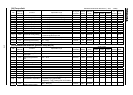
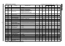
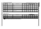
0810 Frequency point selection
0: Invalid, 1: Common serial, 2: RS485,
3: Communication add-on cassette option
0Enabled/ 6.30
0811 Point #1 setting 0 100 [%] 1/0.01 0 Enabled / 6.30
0812 Point #1 frequency 0.0 [Hz] 0.01/0.01 0.0 Enabled / 6.30
0813 Point #2 setting 0 100 [%] 1/0.01 100 Enabled / 6.30
0814 Point #2 frequency 0.0 [Hz] 0.01/0.01 80.0 Enabled / 6.30
0820
Communication rate (RS485)
0: 1200, 1: 2400, 2: 4800, 3: 9600, 4: 19200, 5: 38400
3Enabled/ / / 6.30
0821 RS485 wiring system 0: 2-line system, 1: 4-line system 1Enabled/ / / 6.30
0825
RS485 communication waiting time
0.00: Normal, 0.01 2.00 [s] 0.01/0.01 0.00 Enabled / / / 6.30
0826
Inter-drive communication (RS-
485)
0: Normal, 1: Frequency reference, 2: Output frequency,
3: Torque reference, 4: Output torque
0Enabled/ / / 6.30
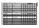
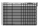
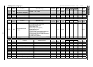
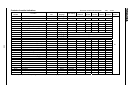
0830 Data type 0, 1 1/1 0 Enabled / / /
0831 Input reference setting #1 0 16 1/1 0 Enabled / / /
0832 Input reference setting #2 0 16 1/1 0 Enabled / / /
0833 Input reference setting #3 0 16 1/1 0 Enabled / / /
0834 Input reference setting #4 0 16 1/1 0 Enabled / / /
0835 Input reference setting #5 0 16 1/1 0 Enabled / / /
0836 Input reference setting #6 0 16 1/1 0 Enabled / / /
0841 Monitor output setting #1 0 16 1/1 0 Enabled / / /
0842 Monitor output setting #2 0 16 1/1 0 Enabled / / /
0843 Monitor output setting #3 0 16 1/1 0 Enabled / / /
0844 Monitor output setting #4 0 16 1/1 0 Enabled / / /
0845 Monitor output setting #5 0 16 1/1 0 Enabled / / /
0846 Monitor output setting #6 0 16 1/1 0 Enabled / / /
0850
Mode at communication error
0 41/10Enabled/ / /
0851
Communication error detection time
0 1000 1/1 200 Enabled / / /
0860 Receiving address 0 1023 1/1 0 Enabled / / /
0861 Transmitting address 0 1023 1/1 0 Enabled / / /
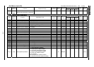
(*1): To be only monitoring available when using S20 option.
(*2): Parameters , , , , and can be reflected at resetting (power OFF ON).
(Reference section): Refer to the inverter's individual manual.
Sensorless vector/vector with sensor ( valid, :invalid)