K-4
(Continued from the preceding page)
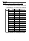
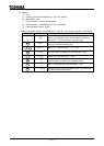
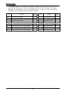
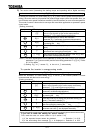
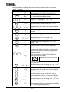
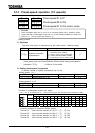
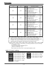
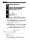
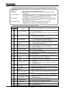
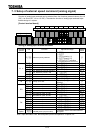
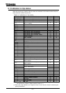
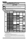
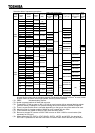
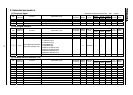
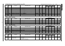
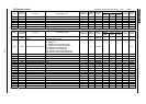
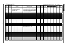
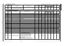
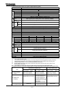
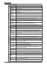
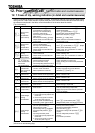
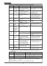
Item Description
Warning
message
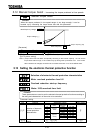
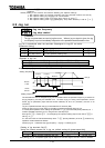
Stall prevention during operation, over-current suppression, overload, power
source-side undervoltage (optional), DC circuit undervoltage, setting error, retry in
process, upper/lower limits.
Fault
causes
trouble
Overcurrent, over-voltage, heat sink overheat, load-side short-circuit, load-side ground
fault, inverter overload, armature over-current during start-up, load-side over-current
during start-up, EEPROM error, RAM error, ROM error, transfer error (dynamic braking
resistor overload), (emergency stop), (undervoltage), (weak current), (over-torque),
(motor overload), (output open-phase). Items in parentheses are selectable.
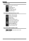
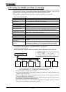
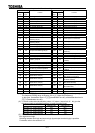
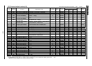
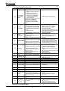
Monitoring
function
Operation frequency, operation frequency command, operating direction
(forward/reverse), output current, DC voltage, output voltage, compensated frequency,
terminal board input /output information, CPU version, control EEPROM version, tripping
history, cumulative operation time, speed feedback, torque, torque command, torque
current, exciting current, PID feedback value, motor overload rate, inverter overload rate,
PBR overload rate, PBR load rate, power supply, output current, peak output current,
peak DC voltage, motor counter pseudo PG, position pulse, RR input, VI/II input, RX
input, RX2 input, FM output, AM output, fixed output for meter adjustment, flash memory
version, main circuit EEPROM version, connection option types, previous default setting,
previous automatic control setting (AU2), sink/source switching status.
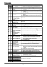
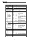
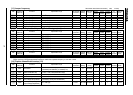
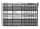
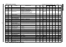
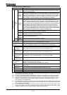
Selectable
unit display
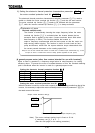
Can select frequency display to match motor speed, line speed, etc. Selection of
display of current in amperes/%, voltage in voltage/%.
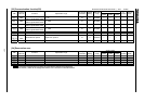
Edit
function
Parameters different from those set by default are retrieved automatically, so that
parameters changed can be detected easily.
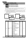
4-digit
7-segment
LED
User
settings
initialization
Original parameters set by user can be stored. Parameters stored can be reset to
original user-defined parameters.
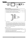
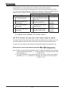
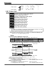
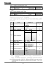
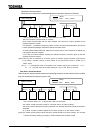
Display functions
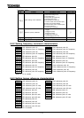
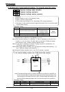
LED
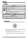
Charge
indicator
Indicates that main circuit capacitors are charged.
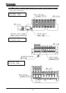
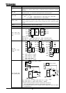
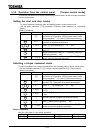
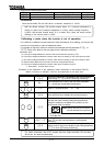
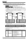
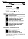
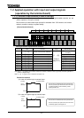
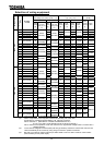
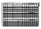
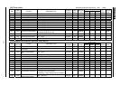
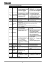
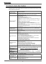
Input/output terminal
logic switching
A-contact/B-contact switchable by making a selection from the programmable I/O
terminal function menu. (*1), (*2) (Default setting: A-contact)
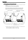
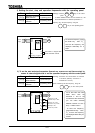
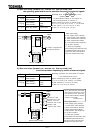
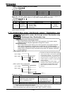
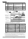
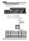
Sink/source
switching
Negative common (CC) and positive common (P24) of control terminal are switchable to
each other. (On shipment, negative common [CC] is selected as default setting.)
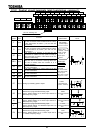
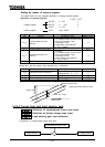
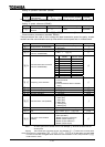
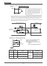
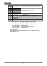
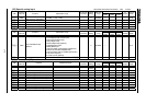
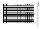
Fault detection signal
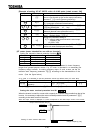
1c contact output (250Vac-2A-cos = 1,250Vac-1A-cos = 0.4, 30Vdc-1A)
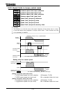
Low-speed/speed
reach signal
output (*2)
Open-collector output (24Vdc, Max. 50mA, output impedance: 33 )
Upper/lower limit
frequency output
(*2)
Open-collector output (24Vdc, Max. 50mA, output impedance: 33 )
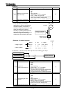
Frequency meter
output/ammeter
output (*3)
Analog output, 1mAdc full-scale ammeter or 7.5Vdc-1mA voltmeter.
Output signals
Pulse train
frequency output
Open-collector output (24Vdc, Max. 50mA)
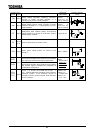
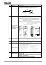
Communication
functions
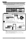
RS485 equipped as standard (connector: modular 8P, optional device required for
communication with more than one unit)
RS232C, TOSLINE-F10M and TOSLINE-S20 are optional.
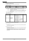
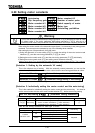
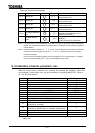
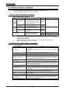
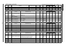
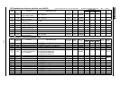
Service
environment
Indoor, altitude 1000m or less, not subject to direct sunlight or corrosive/explosive
gas or steam.
Ambient
temperature
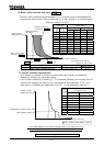
-10 to +50°C (For models 15 kW or less, Max. 50°C, provided that the upper cover
is removed when the ambient temperature exceeds 40°C.)(*6)
Storage temperature
-25 to +65°C
Relative humidity
20 to 93% (no condensation allowed)
Service conditions
Vibration
5.9m/s2 {0.6G} or less (10 to 55Hz) (according to JIS C0911)
(*1): The 16 contact-input terminals (8 of which are optional) are programmable. For each of them, a signal
can be selected from among 136 signals.
(*2): For each programmable ON/OFF output terminal, a signal can be selected from among 120 signals.
(*3): For each programmable analog output terminal, a signal can be selected from among 32 signals.
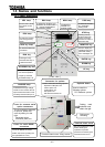
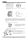
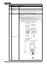
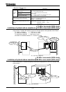
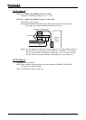
(*4): When the cover is removed, the unit must be placed in the panel to prevent the charger from being
exposed. For the 30kW and larger models, the unit can be used in a temperature range of -10 to
+50°C with the cover left attached.
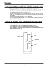
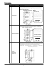
(*5): The models with a capacity of 30kW or more have uncovered wide-opened wiring holes and the unit
has no space in it which is large enough to bend external cables. So, use a optional wiring hole covers
when installing the unit outside.
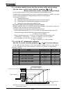
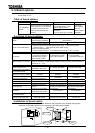
(*6): To use VFA7-2150P in 40 to 50°C, reduce the maximum output current to 80% of rated output current.
Using
VFA7-4150PL
in 40 to 50°C, reduce the maximum output current to 85% of rated output current.
(*7): Protect the inverter from over-current caused by output-side ground fault.