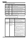
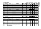
F-31
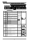
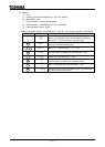
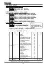
6.14 Drooping control
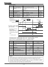
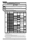
Drooping gain
Speed at a drooping gain 0%
Speed at the drooping gain
Drooping insensitive torque band
Output filter for drooping
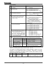
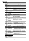
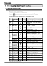
Note : Above parameters are valid only when is set at , or .
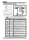
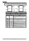
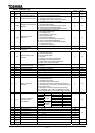
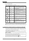
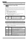
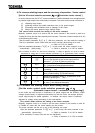
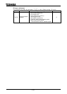
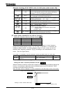
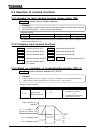
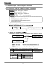
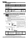
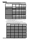
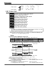
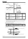
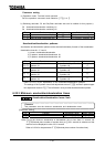
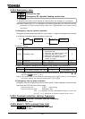
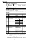
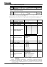
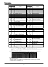
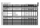
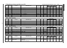
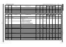
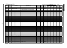
[Parameter setting]
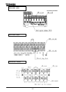
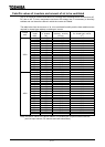
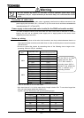
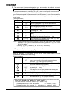
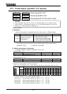
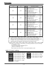
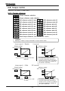
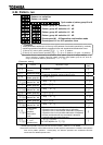
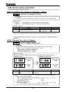
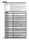
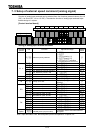
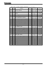
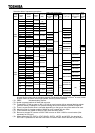
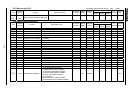
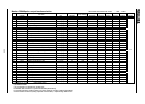
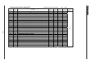
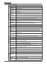
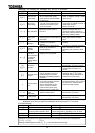
Title Function Adjustment range Default setting
Drooping gain
[%]
Speed at a drooping gain 0[%]
[Hz]
Speed at the drooping gain
[Hz]
Drooping insensitive torque band
[%]
Output filter for drooping
[rad/s]
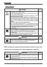
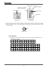
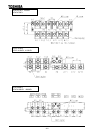
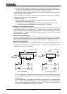
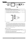
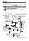
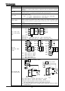
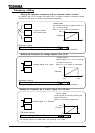
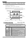
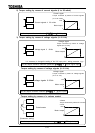
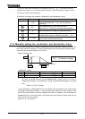
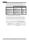
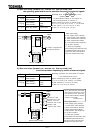
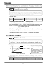
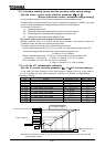
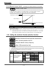
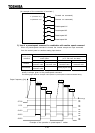
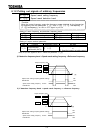
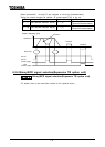
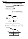
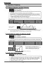
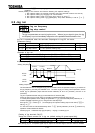
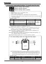
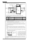
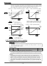
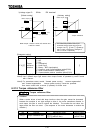
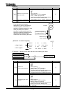
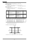
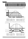
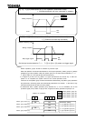
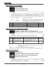
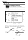
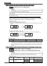
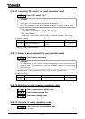
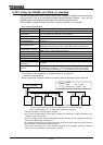
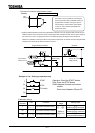
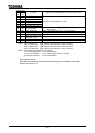
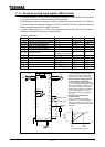
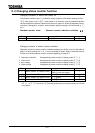
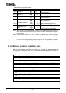
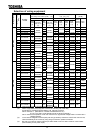
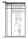
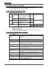
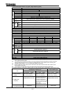
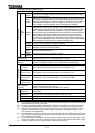
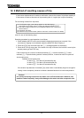
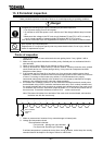
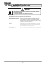
When torque larger than the dead band torque is applied, the frequency is decreased (during power
running) or increased (during regenerative braking).
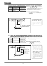
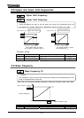
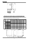
Drooping takes effect within the frequency range above the frequency set with .
In the frequency range between and , the drooping rate varies with the torque.
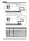
The change in the frequency during drooping can be calculated as described below.
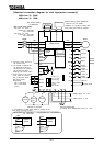
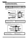
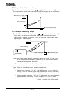
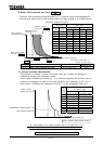
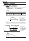
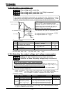
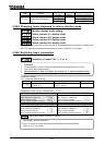
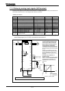
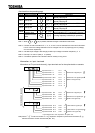
a) Gain by internal torque reference (Gain 1)
If internal torque reference [%] 0
Gain1 internal torque reference dead band
/ 100
Grain 1 needs to be set at 0 or a positive number.
If internal torque reference [%] 0
Gain1 internal torque reference dead band
/ 100
Grain 1 needs to be set at 0 or a negative number.
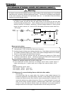
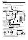
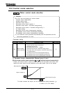
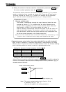
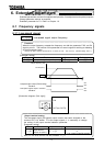
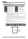
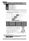
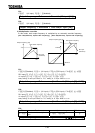
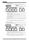
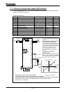
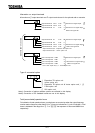
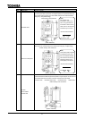
b) Gain by frequency after acceleration (Gain 2)
If
Frequency after acceleration Frequency 1 set with
Gain2 0
Frequency after acceleration Frequency 2 set with
Gain2 Drooping gain / 100
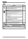
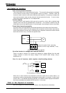
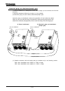
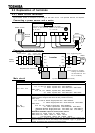
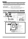
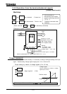
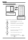
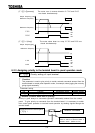
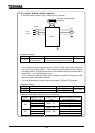
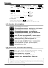
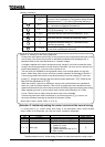
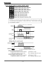
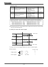
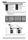
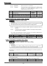
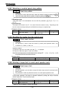
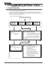
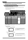
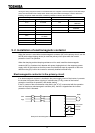
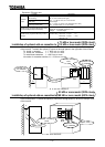
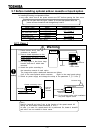
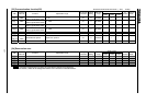
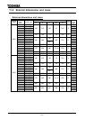
Function
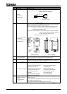
When operating a single load with more than one inverter and one motor, these parameters distribute
the load to the inverters. These parameters can adjust the frequency range, the insensitive torque band
and gains.
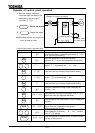
Frequency
Drooping
gain
Dead band
Internal torque reference
Drooping
gain
Dead band