


G-6
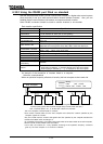
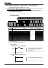
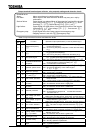
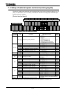
Output terminal function(open collector, relay outputs) settings and detection levels
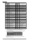
Table of output terminal functions and detection levels
Parameter setting
Positive
logic
Negative
logic
Function Operation output specifications (in case of positive logic)
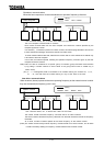
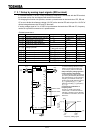
01
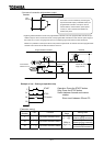
Lower limit frequency
()
"ON": The running frequency is higher than the setting of
(Lower limit frequency).
"OFF": The running frequency is equal to or lower than the setting
of .
23
Upper limit frequency
()
"ON": The running frequency is equal to or higher than the setting
of (Upper limit frequency).
"OFF": The running frequency is lower than the setting of .
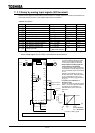
4 5 Low speed signal
"ON": The running frequency is equal to or higher than the setting
of (low-speed signal output frequency).
"OFF": The running frequency is lower than the setting of .
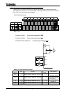
67
Acceleration/deceleration
completion
"ON": The difference between the frequency command and the
running frequency is within the setting of .
"OFF": In acceleration or deceleration.
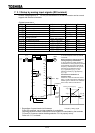
8 9 Specified speed arrival
"ON": The running frequency is in the range of .
"OFF": The running frequency is out of the range of
.
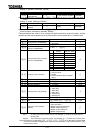
10 11 Failure FL (all trip)
"ON": Inverter is tripped.
"OFF": Inverter trip is cancelled.
12 13
Failure FL (except for
and )
"ON": Inverter is tripped (except EF and OCL).
"OFF": Inverter trip is cancelled (reset).
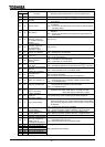
14 15 Over-current pre-alarm
"ON": Inverter output current is over the (Stall prevention
level) set value.
"OFF": Inverter output current is under the set value.
16 17
Inverter overload
pre-alarm
"ON":
A certain rate of inverter overload(
) detection time is over.
"OFF": The detection time is within a certain limit.
18 19
Motor overload
pre-alarm
"ON": A certain rate of motor overload() detection time is over.
"OFF": The detection time is within a certain limit.
20 21 Overheat pre-alarm
"ON": The temperature of the cooling fin is 85 or higher inside
the inverter.
"OFF": The temperature drops to 80 or lower after overheat
pre-alarm was on.
22 23 Over-voltage pre-alarm
"ON": In over-voltage control operation or PB operation.
(200V class: 370 VDC approx., 400V class: 740 VDC approx.)
24 25
Main circuit
under-voltage ()
detected
"ON": The main circuit voltage is lower than the main circuit under-
voltage detection () level.
(200V class: 200 VDC approx., 400V class: 380 VDC approx.)
26 27 Low current detected
"ON": is set at and the state that inverter output current is
set value or larger continued more than set
value.
28 29 Over-torque detected
"ON": The state that torque current component is ()
set value or larger continued more than set value.
30 31
Braking resistor overload
() pre-alarm
"ON": A certain rate of braking resister overload trip()
detection time is over.
"OFF": The detection time is within a certain limit.
32 33 In emergency stop
"ON": In emergency stop operation ("" is indicated).
"OFF": No emergency stop operation is performed.
34 35 In course of retry
"ON": In retry operation ("" is indicated).
"OFF": No retry operation is performed.
36 37
Pattern run switching
output
"ON": In normal operation or pattern operation has finished.
"OFF": In pattern operation.
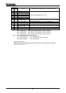
Technical terms
Alarm: Alarm output beyond a certain setting value
Pre-alarm: Alarm output of the state where the inverter may carry out a trip by
continuation
Serious failure: Output signal in a serious failure of the protection function of the inverter.
(Arm over-current(, , ), Load side over-current(), Short-
circuiting(, ), Phase failure(, ), etc.)
Light failure: Output signal in a slight failure of the protection function of the inverter.
(Over-load , , Over-voltage , , , Over-current ,
, , , , , etc.)
Emergency stop: Output signal when the inverter comes into emergency stop.
Stopping manner is set with (emergency stop).