


B-7
Terminal symbol Function
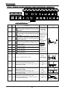
PC
A negative potential terminal of the internal dc main circuit. This terminal can be used to
connect a dc common power source in conjunction with the terminal PA (positive
potential).
PO, PA
Used to connect a DC reactor (DCL: external option). The inverter is shipped with these
terminals shorted. So, remove the shorting bar when connecting a DCL.
R20, S20
Used to connect the control output cables. Provided only for the 400V class 37kW and
larger models. (10VA)
400V 37 75kW: Single-phase 207.5 220V 50Hz, 207.5 230V-60Hz
110 280kW: Single-phase 207.5 230V-50/60Hz
(PR1), (PB1)
Already connected to the internal dynamic braking resistor. If there is no need to use the
resistor, change its connection from (PB1) to (PR1) and change the settings of the
dynamic braking parameters ,. Provided only for the 3.7kW and smaller
models.
(PA1)
Used exclusively for the internal resistor. Do not remove nor connect any external device.
Provided only for the 3.7kW and smaller models.
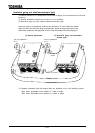
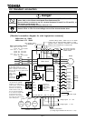
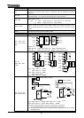
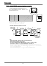
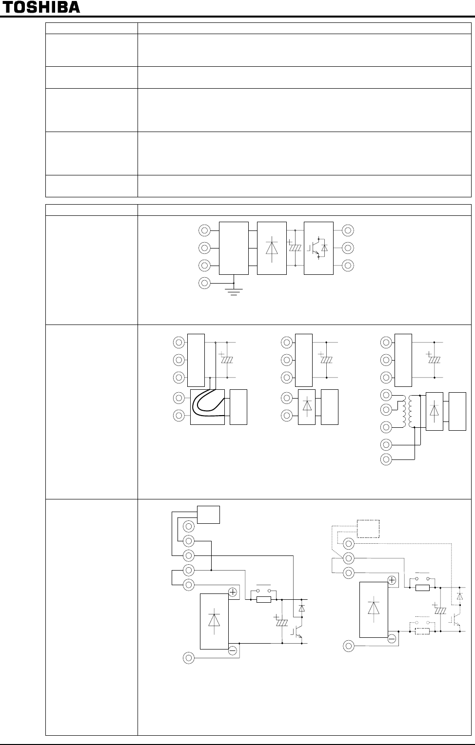
Terminal symbol Inverter internal circuit
R/L1, S/L2, T/L3
U/T1, V/T2, W/T3
G/E
Circuit of A
200V class 0.4 7.5kW, 400V class 0.75 15kW noise filter circuit
200V class 11
90kW, 400V class 18.5 280kW noise by-pass circuit
R0, S0
(R46, R41, R20,
S20)
Fig.1: 200V class 0.4 22kW
400V class 0.7 22kW
Fig.2: 200V class 30 90kW
400V class 30kW
Fig.3: 400V class 37 220kW
P0, PA, PB, PC,
(PA1),(PB1),(PR1)
Fig.1: 200V class 0.4 3.7kW, 400V class 0.75 3.7kW
Fig.2: 200V class 5.5 90kW, 400V class 5.5 280kW
(*1) Rush-current prevention circuit is in plus line or minus line.
18.5 and 22kW models contain it in the rectifier-circuit part.
(*2) The dynamic-braking circuit of 30kW model or larger are served as option
correspondence.
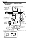
U/T1
V/T2
W/T3
R/L1
S.L2
T/L3
G/E
R/L1
S/L2
T/L3
R46
R41
S0
R20
S20
Braking resistor
Internal braking resistor
Fig.1 Fig.2
(*1)
(*2)
A
Fig.3
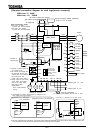
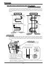
R/L1
S/L2
T/L3
R0
S0
CONTROL
CIRCUIT
Fig.1 Fig.2
CN21
CONTROL
CIRCUIT
CONTROL
CIRCUIT