


F-36
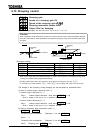
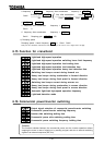
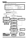
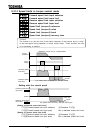
[Setting procedure]
Key operated LED display Operation
The running frequency is displayed. (Make this setting when
the motor is out of operation.) (If the monitor display momde
setting parameter
is set at [Running frequency])
Press the Monitor key to call up the first basic parameter
(automatic acceleration/deceleration).
Select the parameter (extended parameters of
to ) by pressing or key.
Press the Enter key to activate the parameter .
Press the Enter key to display the parameter setting.
Change the parameter setting to (Automatic tuning
execution) by pressing key.
Press the Enter key to save the change. Then, and
the set value are displayed alternately.
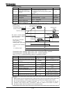
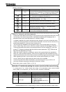
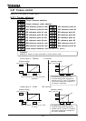
[Selection 3: Individually setting the vector control and the manual tuning]
If a tuning error occurs during auto tuning or the sensorless vector control charact
eristic needs to be improved, you may set motor constants individually.
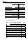
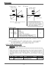
Title Function
Adjustment range
Default setting
Number of motor poles ,,,,,,,
Rated capacity of motor
[Model dependent] [kW]
Model dependent
Motor type
: Toshiba standard motor #1 (*1)
: Toshiba VF motor
: Toshiba V3 motor
: Toshiba standard motor #2 (*1)
: Other motors
(*1) Toshiba standard motor 1: World-energy series of totally-enclosed fan-cooled motors
Toshiba standard motor 2: World-energy 21 series of totally-enclosed fan-cooled motors
MON
ENT
ENT
ENT
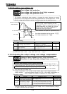
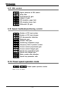
Cautions in setting the auto-tuning parameter
Connect the motor before auto-tuning. Do not proceed to auto-tuning before the motor comes
to a full stop. If the auto-tuning function is activated immediately after stopping motor, it
sometimes fails to work normally because of a residual voltage.
A voltage is applied to the motor during auto-tuning, though it is too low to rotate the motor.
Usually, auto-tuning terminates in some dozens of seconds. If an error occurs, however, the
inverter trips (display ) and no motor constant is set.
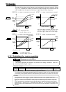
The auto-tuning is incapable of tuning special motors, such as high-speed or a high slip
motors. When using such a motor, set motor constants manually as described in Section 3.
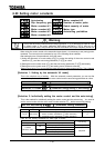
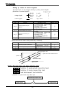
If auto-tuning causes the inverter to trip easily because of an over-voltage or an over-
current , change the setting of the load inertia moment parameter .
Refer to the
Step 2 for the adjustment of .
When the inverter is used for a crane/hoist, equip it with a protective device (mechanical
brake, etc.) with a sufficient capacity. Failure to do so might cause the crane/hoist to loose
speed and fall because the motor cannot produce sufficiently large torque during auto-tuning.
When operating a motor in vector control mode, set the carrier frequency at 2.2 kHz
or over. Failure to do so might cause the vector control to be unstable.
If auto-tuning cannot be made successfully or an auto-tuning error () occurs, set
the motor constants manually as described in Selection 3 below.
Notes about vector control: Refer to 5.10 9)