


A-10
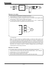
A load, e.g., a reciprocating load, which requires a frequent change in the rotating speed
In this case, if the inverter is in vector control mode, adjust the response time (setting of
moment of inertia) or switch to V/f control mode to stabilize the operation.
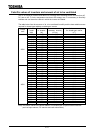
If it is operated in vector control mode, only a motor whose capacity is same as inverter
standard or 1 rank lower is applied.
If it is operated in V/F (other than vector control), the rotating of motor can be unstable in
combination with 3 or more ranks smaller motor.
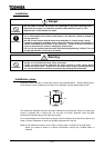
<Stabilizing operation>
Lower the setting value of F300(PWM carrier frequency). (It causes much magnetic
noise of motor, but it is not abnormal.)
In the case that it is still unstable even if the carrier frequency is lowered to 2.2kHz at
( ), set the setting value of F489(
Dead time compensation) to 1 (Disabled) .
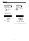
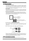
Braking of a motor after power shutoff
If the power is shut off while the motor is still rotating, the motor keeps rotating (or coasting) for
a while before it comes to a complete stop. If you wish to stop it soon after turning off the
power, equip the motor with an auxiliary braking system. There are several types of braking
systems available, for example, mechanical and electrical types. Select a braking system
which matches your system.
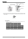
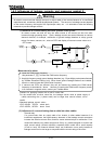
Load producing negative torque
When the inverter is combined with a load producing negative torque, the over-voltage or
over-current protective function of the inverter sometimes works and causes the motor to trip.
In this case, it is necessary to install a dynamic braking resistor, etc., suitable for the load.
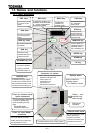
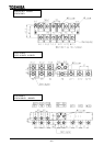
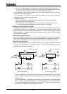
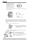
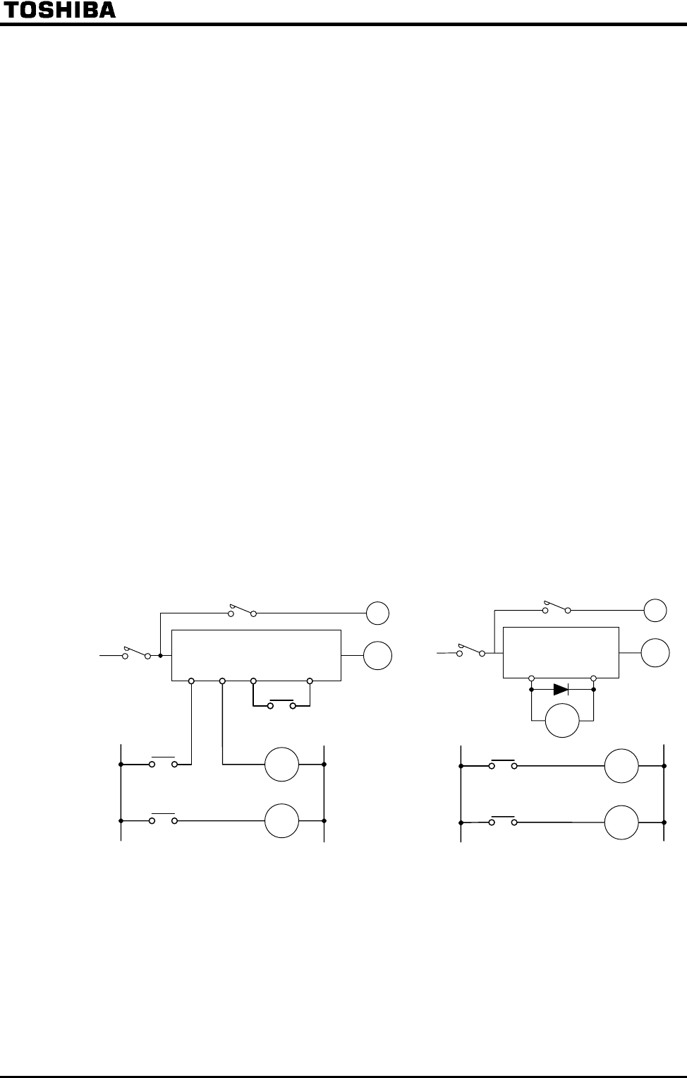
Motor with a braking system
When a brake-equipped motor is connected directly with the inverter, the brake cannot be
released at start-up because of an insufficient voltage. To avoid this, connect the brake cables
separately from the motor main cables.
(Non-exciting brake) (Non-exciting brake)
Circuit configuration 1 Circuit configuration 2
In circuit configuration 1, the brake is turned on and off by means of MC2 and MC3. If the
circuit is configured differently, the motor can trip because of a locked rotor current produced
during braking.
In circuit configuration 2, the brake is turned on and off by means of a low-speed signal
OUT1. However, for certain applications, e.g., elevator applications, it is recommended to
use a low-speed detection signal (function of terminal OUT1) to turn on and off the motor.
Contact your Toshiba dealer before designing a system.
MC1
MC3
MC1
MC3
Three-phase
power supply
MC2
B
IM
FLB FLC ST CC
MC2
MC3
MC1
Three-phase
power supply
LOW
MC3
MC2
B
IM
LOW
OUT1
P24
MC3
MC2