


K-7
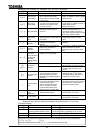
Drawing G
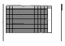
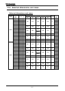
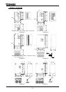
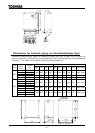
Dimensions for heat-sink going out attachment(simple type)
Dimensions when heat-sink going out attachment (simple type, refer to page A-19) is carried out
becomes as follows. For dimensions not in the table below, refer to the dimensions for normal attachment
(Drawing E, F, G). Mass is as same as the time of the normal attachment.
Dimensions [mm] Panel-cut dimensions [mm]
Voltage
class
Applicable
motor
[kW]
Inverter
type
W2 H2 D2 D3 W3 H3 W4 H4 H5 Screw hole
37
VFA7-2370P1
45
VFA7-2450P1
55
VFA7-2550P1
445 630 161 287 375 590 417 609 9.5
4-M10 screw
75
VFA7-2750P1
573 680 186 330 500 630 527 652 12.5
4-M10 screw
200V
90
VFA7-2900P1
762 950 173 370 680 890 712 920 15
4-M12 screw
37
VFA7-4370P1
45
VFA7-4450P1
55
VFA7-4550P1
75
VFA7-4750P1
445 630 161 287 375 590 417 609 9.5
4-M10 screw
90/110
VFA7-4110KP1
132
VFA7-4132KP1
573 680 186 330 500 630 527 652 12.5
4-M10 screw
160
VFA7-4160KP1
220
VFA7-4220KP1
400V
280
VFA7-4280KP1
762 950 173 370 680 890 712 920 15
4-M12 screw
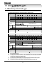
W2
D2
H2
W3
H3
W4
H4
S
crew
h
o
l
e
Pane-cut dimensions
H5
D3
5
12
R6
2- 15
W1
(Mounting dimension)
H
H1(Mounting dimension)
W
5
D
6- 25
15