B-4
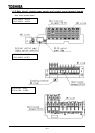
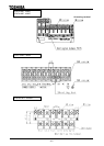
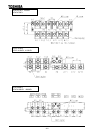
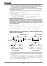
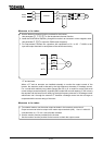
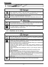
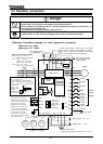
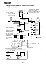
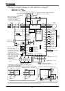
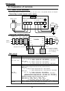
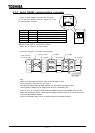
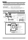
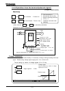
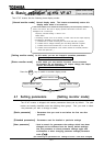
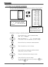
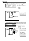
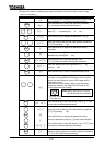
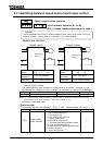
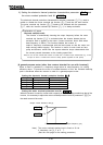
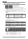
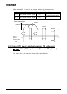
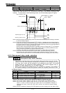
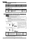
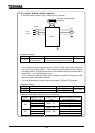
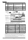
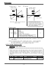
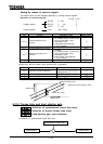
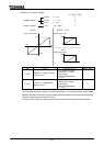
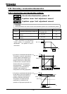
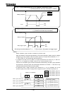
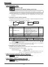
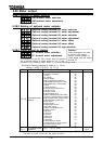
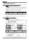
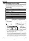
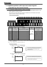
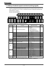
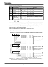
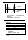
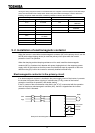
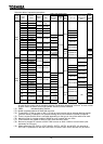
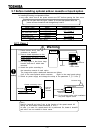
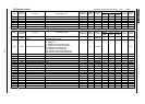
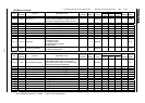
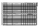
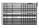
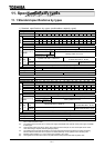
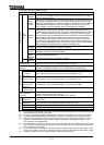
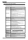
[Standard connection diagram for sink logic(minus common)]
200V class: 30 55kW
400V class: 30 75kW
Main circuit power supply
200V class 30 55kW
3-phase 200 220V-50Hz
200 230V-60Hz
400V class
30 75kW
3-phese 380 440V-50Hz
380 460V-60Hz
Control
circuit
Motor
FL
G/E
CC
RX RR
PP
F
RES
CC
R/L1
S/L2
T/L3
U/T1
V/T2
W/T3
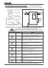
Control panel
FLC
FLB
FLA
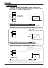
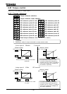
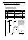
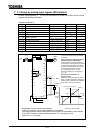
Voltage signal -10 +10V
Voltage signal 0 10V
Forward
Preset
speed 1
S1
Preset
speed 4
ST
R
S2
S3
S4
OUT2
P24
OUT1
AMFM
FP
mmete
Frequency
meter
Digital
voltmete
Main circuit
Reverse
Standby
Reset
Preset
speed 3
Preset
speed 2
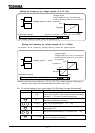
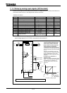
Current signal
MCCB
R0
S0
Connector for
common serial
communication
RS485 connector
for serial
communication
Common
External potentiometer
(or voltage signal between RR and CC: 0 10V)
(R20)
(S20)
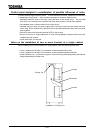
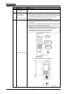
*1: Connect a power source for
the control circuit.
*2: The inverter is shipped with
the terminals PO and PA
shorted with a bar. Remove
this shorting bar when
installing a DC reactor (DCL).
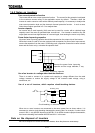
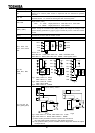
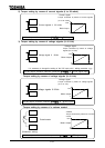
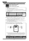
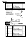
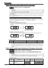
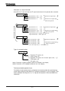
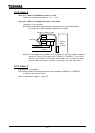
*3: Power output for the control
circuit, which is provided
only for the 400V 37kW
and larger models.
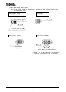
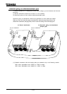
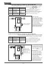
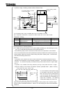
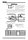
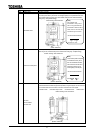
Single-phase
207.5 220V-50Hz
207.5 230V-60Hz
(10VA)
Voltmeter or ammeter
Control
circuit
R46
S0
R20
S20
Single-phase 415 440V-50Hz
415 460V-60Hz
R41
Control
circuit
R46
S0
R20
S20
Single-phase 380 415V-50/60Hz
R41
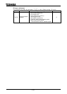
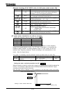
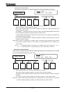
*4: Connections of control power cables by voltage for the
400V 37kW and larger models.
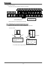
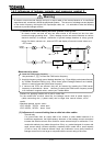
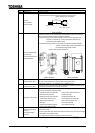
DC reactor (DCL)
*2 (Optional)
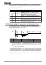
External braking resistor (Optional)
Refer to 6.13.4 for details
Installation of a dynamic braking drive
circuit inside the inverter is required.
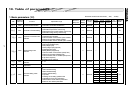
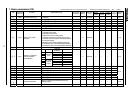
Factory
default
settings