


I-3
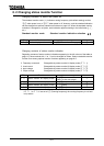
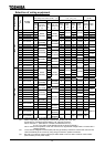
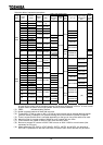
Among the wiring equipment shown in the above table, the magnetic contactors (MC) and overload relays
(THR) are new models of the TeSys series. When using old models of the Mighty J series, refer to the
following comparison table that shows consistency between models of the two series.
Magnetic contactor (MC) Overload relay(THR)
Mighty J series TeSys series Mighty J series TeSys series
C11J LC1D096 T13J
LR3D076
LR3D166
C13J LC1D126 T20J LR3D216
C20J LC1D186 T35J
LR3D226
LR3D326
C25J LC1D256 T65J LR3D356
C35J LC1D326
C50J
LC1D386
LC1D506
C65J LC1D656
C80J LC1D806
C100J LC1D956
9. 2. Installation of electromagnetic contactor
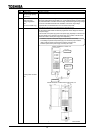
When the inverter is used without electromagnetic contactor (MC) in the primary circuit, use the
MCCB (with voltage tripping device) to make the primary circuit open when the inverter
protection circuit is in operation.
When the damping resistor/damping resistance unit is used, install the electromagnetic
contactor (MC) or fuseless circuit breaker with power tripping device in the temporary power
supply circuit of the inverter so that the power circuit becomes open by operation of the error
detection relay (EL) built in the inverter or externally installed overload relay.
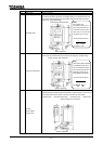
Electromagnetic contactor in the primary circuit
If an electromagnetic contactor is installed in the power supply circuit of the inverter, it prevents
the inverter from power failure, tripping of overload relay (Th-Ry), cutout of the inverter
protection circuit after its operation, and double starting.
If the FL contact of the error detection relay built in the VF-A7 is connected with the operation
circuit of the primary electromagnetic contactor (MC), the MC is tripped when the inverter
protection circuit is actuated.
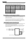
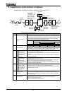
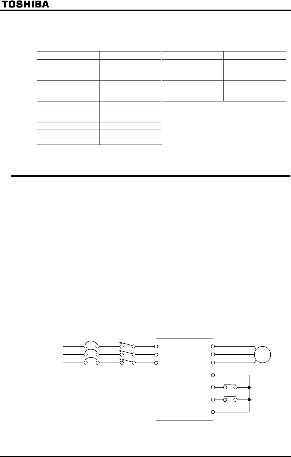
Example of electromagnetic contactor connection in primary circuit
Power
supply
Operation preparation
Forward
Reverse
Moter