


G-10
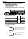
7. 3 Setup of external speed command (analog signal)
Function of analog input terminals can be selected from four functions (external volume, 0 to 10
VDC, 4 to 20 mA DC, -10 to +10 VDC). The selective function of analog input terminals helps
flexible design of a system.
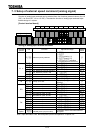
[Control terminal board]
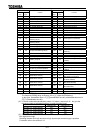
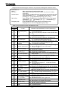
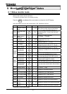
Setting of analog input terminal functions
Terminal
symbol
Title Function Adjustment range
Default
value
Reference priority selection
:
:
: priority (*1)
: priority (*2)
: / switching
(Input terminal function selection 104)
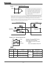
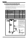
VI/II reference point #1
[%]
VI/II reference point #1 frequency
[Hz]
VI/II reference point #2
[%]
VI/II reference point #2 frequency
[Hz]
VI/II reference point #1 rate
[%]
VI II
VI/II reference point #2 rate
[%]
Speed setting mode selection #2
Same as ( )
fmod/f207 switching frequency
[Hz]
All
Analog input filter
(disabled) to (max. filter
capacity)
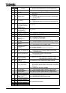
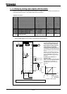
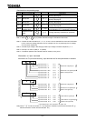
RR reference point #1
[%]
RR reference point #1 frequency
[Hz]
RR reference point #2
[%]
RR reference point #2 frequency
[Hz]
RR reference point #1 rate
[%]
RR
RR reference point #2 rate
[%]
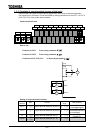
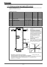
RX reference point #1
[%]
RX reference point #1 frequency
[Hz]
RX reference point #2
[%]
RX reference point #2 frequency
[Hz]
RX reference point #1 rate
[%]
RX
RX reference point #2 rate
[%]
Option
RX2,BIN,pulse input point setup
For details, refer to the instructions of
the option.
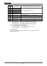
Note: Input terminals of RX2, BIN and pulse input are at expansion TB option unit.