


H-8
Continued from the preceding page
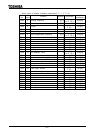
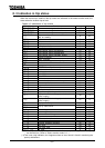
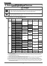
Com,No. Contents of indication Key operated LED display Description
FE10 Past trip #1
(Alternately blinking at intervals of 0.5
second) Past trip #1
FE11 Past trip #2
(Alternately blinking at intervals of 0.5
second) Past trip #2
FE12 Past trip #3
(Alternately blinking at intervals of 0.5
second) Past trip #3
FE13 Past trip #4
(Alternately blinking at intervals of 0.5
second) Past trip #4
FE14
Cumulative operation
time
Indication of total (accumulated)
operation hours(Indication of 0.1
represents 10 hours.)
Standard monitor
mode
2
Status monitor mode(Blinking for trip
indication)
Reverts to the first trip indication.
Note 1: Failures that occur during initialization of the CPU on turning on the power or after resetting the
inverter are not held by the failure trip holding function, and status monitor indications appear for
such the failure.
Note 2: Contents of status indications of 2, 3, 4 and 5 can be selected from 30 kinds of information.
Contents of indications that are set up at to (status monitor #1 to #4 display
mode) are displayed.
Unit of current and voltage indications can be changed from % to A (amperage) or V (voltage)
and vice versa respectively with (Current/voltage display mode).
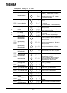
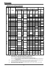
8. 4 Indication of alarm, pre-alarm, etc...
When the inverter alarm, pre-alarm, etc. occurred, the contents are displayed. (Some are
not displayed.) Listed below ones can be monitored via communication(FC91). Refer to
12.1 for the other alarms.
Bit Contents of indication Panel indication
0 Over-current pre-alarm
1 Inverter overload pre-alarm
2 Motor overload pre-alarm
3 Overheat pre-alarm
4 Over-voltage pre-alarm
5 Main circuit under-voltage () detected
6 Poor control power supply () pre-alarm
7 Low current detected (no indication)
8 Over-torque detected (no indication)
9 Braking resistor overload () pre-alarm (no indication)
10 Cumulative operation time alarm (no indication)
11
Abnormal communication alarm #1
(caused by scanning)
12
Abnormal communication alarm #2
(caused by RS485 logic or message transmission)
13 Reservation area
14 Reservation area
15 Reservation area
Note) For each bit, "0" indicates normal condition and "1" indicates appearance of
alarm, etc..