


J-26
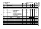
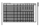
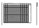
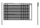
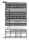
Output terminal function setting (1/2)
Positive
logic
Negative
logic
Function
Speed
control
Torque
control
Position
control
V/f
constant
Reference
section
01
Lower limit frequency() / / /
23
Upper limit frequency()
/ / /
45
Low speed signal / / /
67
Acceleration/deceleration completion
/
89
Specified speed arrival / / /
10 11
Failure FL (all trip) / / /
12 13
Failure FL (except for and )
/ / /
14 15
Over-current pre-alarm / / /
16 17
Inverter overload pre-alarm
/ / /
18 19
Motor overload pre-alarm / / /
20 21
Overheat pre-alarm
/ / /
22 23
Over-voltage pre-alarm / / /
24 25
Main circuit under-voltage () detected / / /
26 27
Low current detected
/ / /
28 29
Over-torque detected / / /
30 31
Braking resistor overload () pre-alarm
/ / /
32 33
In emergency stop / / /
34 35
In course of retry
/ / /
36 37
Pattern run switching output /
38 39
PID deviation limit /
40 41
Run/stop
/ / /
42 43
Serious failure (, , , phase failure, etc.) / / /
44 45
Light failure (, , , , )
/ / /
46 47
Commercial/INV switching output #1(for inverter operation output) /
48 49
Commercial/INV switching output #2(for commercial operation output)
/
50 51
Cooling fan ON/OFF / / /
52 53
In Jog run /
54 55
Panel operation/terminal board operation switching / / /
56 57
Cumulative operation time alarm / / /
58 59
Abnormal communication alarm #1 (caused by scanning)
/ / /
60 61
Forward/reverse switching / / /
62 63
Ready for operation #1
/ / /
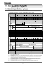
7.2.2
Sensorless vector/vector with sensor : valid, : invalid