


B-6
2.3 Explanation of terminals
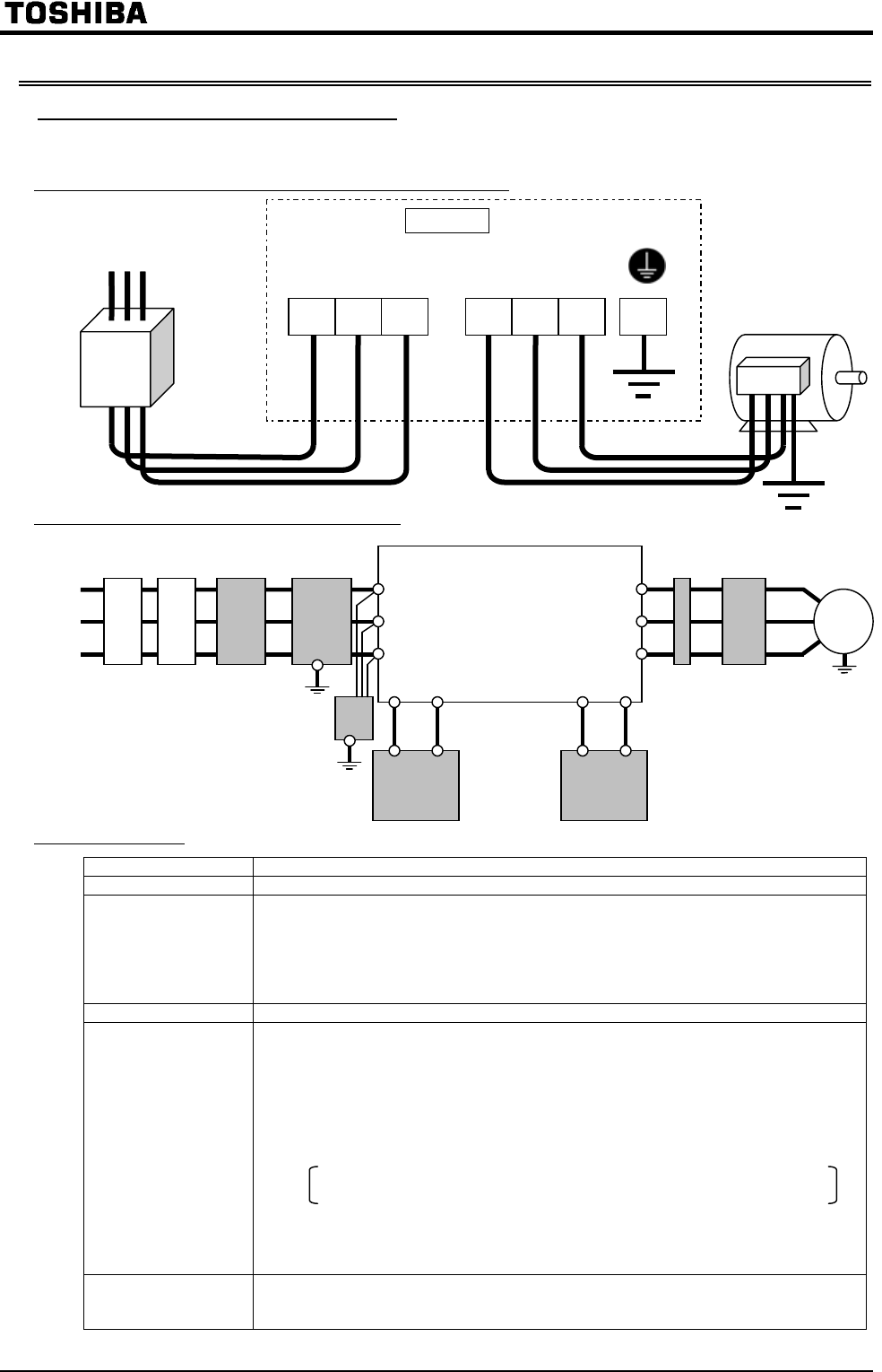
2.3.1 Main circuit terminals
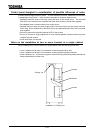
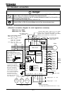
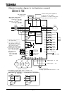
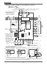
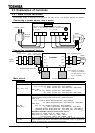
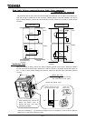
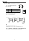
Figure below shows an example of the wiring of the main circuit. Use optional devices, as required.
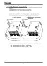
Connecting a power source and a motor
Connecting peripheral devices
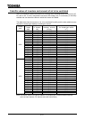
Main circuit
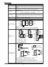
Terminal symbol Function
G/E Grounding terminal for the inverter's enclosure.
R/L1 S/L2 T/L3
200V class:
0.4 7.5 and 75, 90kW: 3-phase 200 230V-50/60Hz
11 55kW: 3-phase 200 220V-50Hz,200 230V-60Hz
400V class:
0.75 22, 110 280kW: 3-phase 380 460V-50/60Hz
30 75kW: 3-phase 380 440V-50Hz,380 460V-60Hz
U/T1 V/T2 W/T3
Used to connect a motor (3-phase inductive motor)
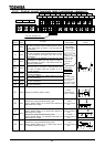
R0 S0
(R46, R41)
Used to connect a power source for the control circuit (Optional for the 22kW and
smaller models, though these terminals are provided for them)
200V class:
0.4 7.5 and 75, 90kW: Single-phase 200 230V-50/60Hz
11 55kW: Single-phase 200 220V-50Hz,200 230V-60Hz
400V class:
0.75 22, 110 280kW: 3-phase 380 460V-50/60Hz
30 75kW: 3-phase 380 440V-50Hz,380 460V-60Hz
Between R46-S0: Single-phase 415 440V-50Hz, 415 460V-60Hz
Between R41-S0: Single-phase 380 415V-50Hz, 380 415V-60Hz
*Maximum allowable output of control power source:
200V class: 0.4 30kW 50VA, 37 90kW 60VA
400V class: 0.75 30kW 50VA, 37 75kW 150VA,
110 and 132kW 200VA, 160 280kW 350VA
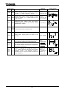
PA, PB
Used to connect a dynamic braking resistor (For the optional dynamic braking unit,
connect it between PA and PC.)the settings of the parameters , and/or
, as required, when connecting an external resistor.
Motor
Zero-phase
reactor
Power
source
Inverter
DC reactor
Surge suppressing filter
Dynamic braking resistor(See Note.)
Sim
p
lified radio noise filte
r
Radio noise
reduction filter
(high-attenuation)
Input
reactor
Magnetic
contactor
Non-fuse
breaker
/L1
/L2
/L3
PA P0 PA PB
/T2
/T3
/T1
Note) Connect a dynamic
braking unit between
the terminals PA and
PC, if necessary.
IM
Power source
R/L1 S/L2 T/L3
Moto
r
No-fuse
breaker
Connect the power
source to the terminals
R, S and T.
Connect the motor
cables to the terminals
U, V and W.
VF-A7
E
U/T1 V/T2 W/T3 G/E