


H-1
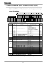
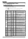
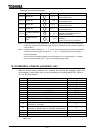
8. 1 Status monitor mode
Status of the inverter can be monitored.
To monitor the inverter when it is normally running,
Press the key
twice
and the current status is indicated on the LED display.
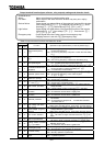
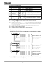
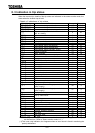
Setup procedure to monitor the inverter status. (EX. Operation at 60 Hz)
Com.No.
Details of indication
Key operated
LED display
Description
Standard monitor
mode
Running frequency indication (in operation)
(In the case monitor display mode setting
is set at [running frequency])
FE01
Parameter setup
mode
Indication of "Automatic acceleration
/deceleration()" that is the first basic
parameter
FE01
Status monitor
mode (rotating
direction)
Indication of rotating direction
(: forward, : reverse)
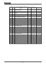
Frequency
command
Indication of frequency command value.
(In case of =)
Load indication
Indication of inverter output current (load
current)(In case of =)
DC voltage
Indication of inverter DC voltage (Default
setting unit: [%]) (In case of =)
Output voltage
Indication of inverter output voltage (Default
setting unit: [%]) (In case of =)
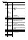
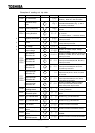
Input terminal
information #1
Indication of ON/OFF status of control input
terminals (F, R, RES, ST, S1, S2, S3, S4) in
bits
Input terminal
information #2
Indication of ON/OFF status of optional control
input terminals (B8,B9,B10,B11) in bits
FE06
FE50
FE51
Input terminal
information #3
Indication of ON/OFF status of optional control
input terminals (B11,B12,B13,B14) in bits
Output terminal
information #1
Indication of ON/OFF status of control output
terminals (OUT1,OUT2,FL) in bits
Output terminal
information #2
Indication of ON/OFF status of optional control
output terminals (R1,R2,OUT3,OUT4) in bits
FE07
FE52
FE53
Output terminal
information #3
Indication of ON/OFF status of optional control
output terminals (ALM0,ALM1,ALM2,ALM3) in
bits
FE48
Sink/source
switching status
Indication of sink or source status
(: source, : sink)
FE47
Type of connected
option
Indication of connected options
FE54 last set data Indication of value set last
FE55 last set data Indication of value set last
FE08 CPU version Indication of version of the CPU
FE43
Flush memory
version
Indication of version of the flush memory
FE09
Control EEPROM
version
Indication of version of the control EEPROM
FE44
Drive EEPROM
version
Indication of version of the drive EEPROM
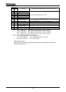
(Continued on the following page)
8. Monitoring operation status
MON
1
2
3
4
5