


I-1
Danger
Mandatory
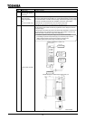
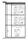
When using the inverter without the front cover, be sure to place the inverter unit inside a
cabinet. If they are used outside the cabinet, it may cause electric shock.
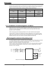
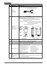
Be grounded
Be sure to ground every unit. If not, it may cause electric shock or fire on the occasion of
failure, short-circuit or electric leak.
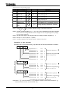
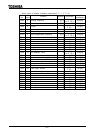
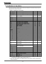
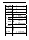
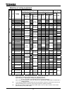
9. 1 Selection of wiring equipment
Wire size AWG cross-section [mm
2
]
Voltage
class
Applicable
motor [kW]
Inverter model
Main circuit(*1)
DC reactor
(optional)
Brakin
g
resisto
r
(optional)
Earth cable
0.4 VFA7-2004PL
0.75 VFA7-2007PL
1.5 VFA7-2015PL
2.2 VFA7-2022PL
14(2)
3.7 VFA7-2037PL
14(2)
12(3.5)
14(2) (*5)
5.5 VFA7-2055PL 12(3.5) 10(5.5)
12(3.5)
7.5 VFA7-2075PL 10(5.5) 8(8) 10(5.5)
11 VFA7-2110P 6(14)
15 VFA7-2150P
6(14)
4(22)
10(5.5)
6(14)
18.5 VFA7-2185P 4(22) 8(8)
22 VFA7-2220P 2(38)
2(38) 4(22)
30 VFA7-2300P 2/0(60)
6(14)
37 VFA7-2370P1
2/0(60)
4/0(100)
2(38)
45 VFA7-2450P1
55 VFA7-2550P1
4/0(100)
4(22)
2/0(60)
75 VFA7-2750P1
300
(150)
200V
class
90 VFA7-2900P1
300(150)
400(200)
2(38) or
6 2(14 2)
4/0(100)
0.75 VFA7-4007PL
1.5 VFA7-4015PL
2.2 VFA7-4022PL
3.7 VFA7-4037PL
14(2) (*5)
5.5 VFA7-4055PL
14(2)
7.5 VFA7-4075PL
14(2)
12(3.5)
11 VFA7-4110PL 12(3.5) 10(5.5)
12(3.5)
15 VFA7-4150PL 10(5.5) 8(8)
14(2)
10(5.5)
18.5 VFA7-4185P 8(8) 8(8)
22 VFA7-4220P
6(14)
30 VFA7-4300P
6(14)
4(22)
10(5.5)
6(14)
37 VFA7-4370P1 4(22)
45 VFA7-4450P1
2(38)
55 VFA7-4550P1
2(38)
2/0(60)
4(22)
75 VFA7-4750P1 2/0(60)
6(14)
2(38)
90/110 VFA7-4110KP1
132 VFA7-4132KP1
4/0(100)
4/0(100)
2/0(60)
160 VFA7-4160KP1
300(150) 300(150)
4(22)
220 VFA7-4220KP1
400(200)
300 2
(150 2)
2/0(60) or
4 2(22 2)
4/0(100)
400V
class
280 VFA7-4280KP1
300 2
(150 2)
400 2
(200 2)
4/0(100) or
2/0 2(60 2)
300
(150)
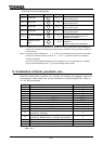
(*1): Indicates wire sizes of input terminals R, S, T and output terminals U, V, W. Wiring distance is supposed to
be 30 m at maximum.
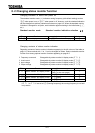
(*2): The recommended cable size is that of the cable (e.g. 600V class,HIV cable) with continuous maximum
permissible temperature of 75°C.
(*3): For the control circuit, use shielded wires whose size (cross-section) is 0.75 mm
2
or more. The size (cross-
section) of wires supplying control power is 2.0 mm
2
or more.
(*4): For the earth cable, use wires larger than the specified ones in size (cross-section). (UL standard)
(*5): Recommended wire size for external braking resistor. Refer to 6.13.4 for use of external braking resistor.
(*6): Do not connect more than two wires to a terminal block (except for terminal blocks of 2900, 4160K to 4280K
and PA terminals of models that have only one PA terminal). If wiring with more than two wires is needed,
set a external relay terminal.
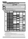
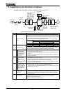
9. Selection of peripheral devices