


E-26
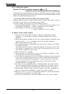
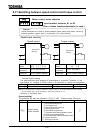
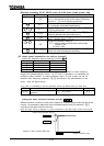
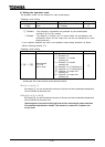
[Example of setting: VF-A7 2007PL with a 0.4 kW motor (rated current: 2A)]
Key operated LED display Operation
The running frequency is displayed. (Make this setting when the
motor is out of operation.)(If the monitor display mode setting
parameter is set at [Running frequency])
Press the MON key to call up the first basic parameter
(automatic acceleration/deceleration).
Switch to (extended parameters of from to
) by pressing the or key.
Press the Enter key to call up the parameter
(electronic thermal motor protection level 1).
Press the Enter key to display the parameter setting (set
value). (Default setting: %)
Change the parameter setting to
= (motor's rated current/inverter's rated output
current) x 100
= 2.0/5.0 x 100)
Press the Enter key to save the change. Then,
and the set value are displayed alternately.
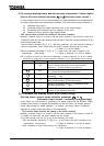
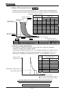
[VF motor (motor intended for use with an inverter)]
Setting the electronic thermal protective function
Set value Overload protection Overload stall
protect not stall
protect stall
not protect not stall
not protect stall
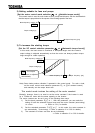
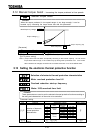
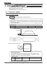
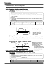
VF motors (intended for use with an inverter) can be operated in lower frequency
ranges than general-purpose motors. If a VF motor is operated in an extremely low
frequency range, however, its cooling efficiency drops. In such a case, set the OL
reduction start frequency parameter according to the characteristics of the
motor. (See the figure below.)
As a guide, it is advisable to set this parameter around the default value (VF motor 6Hz).
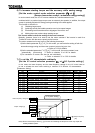
Title Function Adjustment range
Default setting
Overload reduction start-up
frequency
[Hz]
Note) is enabled when is set at , , , or .
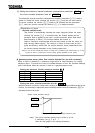
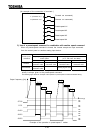
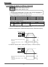
Setting the motor overload protection level #1
When the inverter is used for a motor with a capacity or a current rating smaller than that of the
inverter, it is necessary to adjust the motor overload protection level #1 parameter
according to the rated current of the motor.
When the output current is displayed in %,100% corresponds to the rated output current of the inverter.
MON
ENT
ENT
ENT
6.0
Output frequency [Hz]
Output current reduction rate [%]
Setting of motor overload start level
0.6
1.0