


E-10
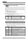
5.4 Setting and calibrating meters
FM Terminal meter selection
FM Terminal meter adjustment
AM Terminal meter selection
AM Terminal meter adjustment
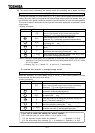
Note 1: The signal output from the FM and AM terminal is an analog voltage signal. (positive (+) side output.
For signed data, an absolute value is output.)
Note 2: To the FM terminal, connect either a full-scale 0~1mAdc ammeter or a full-scale 0~7.5Vdc (or 10Vdc)
voltmeter, if necessary. The FM terminal can also be used as a 0(4)~20mAdc output terminal. To the
AM terminal, connect a full-scale 0-1mAdc ammeter.
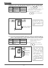
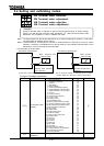
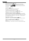
Connect meters as shown below.
Connection to terminal FM Connection to terminal AM
An frequency meter QS60T is optionally available.
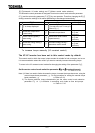
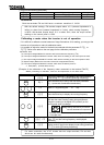
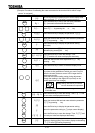
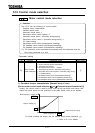
[Terminal FM-related parameters]
Title
Function Adjustment range
Adjustment level
Default setting
FM terminal meter
selection
: Running frequency
: Frequency command
: Current
: DC voltage
: Output voltage
: After-compensation frequency
: Speed feedback (real-time value)
: Speed feedback (1 second filter)
: Torque
: Torque reference
: Internal torque reference
: Torque current
: Exciting current
: PID feedback value
: Motor overload factor (OL2 data)
: Inverter overload factor (OL1 data)
: PBr overload factor (PBrOL data)
: PBr load factor (pulse duty)
: Input power
: Output power
: Peak output current
: Peak DC voltage
: Motor counter dummy PG
: Position pulse
: RR input
: VI/II input
: RX input
: RX2 input
: FM output
: AM output
: Fixed output for meters
: Analog output for communication
: Acc/dec torque removal
:Current (with filter)
(a)
(a)
(b)
(b)
(b)
(a)
(a)
(a)
(b)
(b)
(b)
(b)
(b)
(a)
(c)
(c)
(c)
(c)
(e)
(e)
(b)
(b)
(d)
(d)
(c)
(c)
(c)
(c)
(c)
(c)
(c)
(b)
(b)
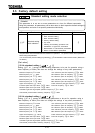
FM terminal meter
adjustment
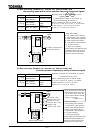
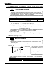
Function
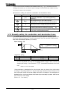
Inverter’s operation data is outputted to the FM terminal (AM terminal) as analog voltage
signals. The “FM terminal-connected meter adjustment ” (AM terminal-connected meter
adjustment ) parameter is used to calibrate the meter.
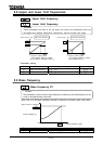
Meter : Frequency meter
(Default setting)
The reading of the
frequency meter fluctuates
during calibration.
Meter: Ammeter
(Default setting)
The reading of the
ammeter fluctuates during
calibration.
Use an ammeter capable of measuring up to a curren
t
1.5 times larger than the rated current of the inverter.