


J-17
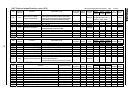
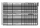
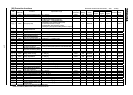
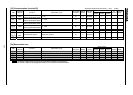
[28] Protection functions
Vector control
Title
Communi
cation No
Function Adjustment range
Min. unit (panel/
communication)
Default
setting
Write during
running
Speed
control
To rque
control
Position
control
V/f
Constant
Reference
section
0600
Motor overload protection level #1
10 100 [%] 1/0.01 100 Enabled / / / 5.13
0601 Stall prevention level 0 199 [%], 200: Disabled 1/0.01 150 Enabled / / / 6.25.2
0602
Selection of inverter trip holdin
g
0: Cleared if power is turned off
1: Held even if power is turned off
0 Disabled / / / 6.25.3
0603 Emergency stop
0: Coast stop 1: Deceleration stop
2: Emergency DC injection braking stop
3: Coast stop without FL output
4: Deceleration stop without FL output
5:
Emer
g
enc
y
DC in
j
ection brakin
g
without FL output
0 Disabled / / / 6.25.4
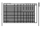
0604
Emergency DC injection
braking control time
0.0 10.0 [s] 0.1/0.01 0.1 Enabled / / / 6.25.4
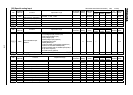
0605
Output phase failure detection
0: Disabled, 1 5: Enabled 0 Disabled / / /
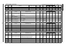
0606
Overload reduction start-up frequenc
y
0.0 30.0 [Hz] 0.01/0.01 6.0 Enabled / / / 5.13
0607
Motor 150%-overload time limit
10 2400 [s] 1/1 600 Enabled / / / 5.13
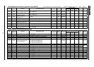
0608
Relay injection timing for
rush-current suppression
0.3 2.5 [s] 0.1/0.01 0.3 Disabled / / /
0609
Mode of rush-current suppression rela
y
0: Standard, 1: in relation to ST 0 Disabled / / /
0610 Low current trip 0: Disabled, 1: Enabled 0 Disabled / / / 6.25.7
0611 Low current detection level 0 100 [%] 1/0.01 0 Enabled / / / 6.25.7
0612 Low current detection time 0 255 [s] 1/1 0 Enabled / / / 6.25.7
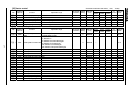
0613
Detection of output short-
circuit during start-up
0: Standard
1:
Onl
y
one time at power in
j
ection or at first start after rese
t
0 Disabled / / / 6.25.8
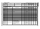
0614
A
d
j
ustment of detection pulse for
output short-circuit durin
g
start-up
1 100 [ s] 1/1 50 Disabled / / / 6.25.8
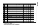
0615 Over-torque trip 0: Disabled, 1: Enabled 0Enabled/ / / 6.25.9
0616
Over-torque detection level
during power running
0 250 [%]
1/0.01 150 Enabled / / / 6.25.9
0617
Over-torque detection level
during regeneration
0 250 [%]
1/0.01 150 Enabled / / / 6.25.9
0618 Over-torque detection time 0.0 100.0 [s] 0.1/0.01 0.5 Enabled / / / 6.25.9
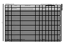
0620 Cooling fan control mode 0: Automatic, 1: Always ON 0Enabled/ / / 6.2510
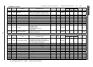
0621
Cumulative operation time alarm settin
g
0.1 999.9 [ 100h] 0.1/0.1 175.0 Enabled / / / 6.25.11
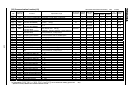
0622
A
bnormal speed detection filter
0.01 100.0 [s] (*1) 0.01/0.01 10.00 Enabled / / / /
0623
Over-speed detection frequenc
y
ran
g
e
0: Disabled, 0.1 30.0 [Hz] 0.01/0.01 0.0 Enabled / / /
0624
Speed drop detection frequenc
y
ran
g
e
0: Disabled, 0.1 30.0 [Hz] 0.01/0.01 0.0 Enabled / / /
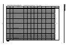
0625
Over-volta
g
e stall protection
level (high response)
50 250 [%] 1/0.01 135 Enabled / 6.13.5
0626
Over-volta
g
e stall protection level
50 250 [%] 1/0.01 130 Enabled / 6.13.5
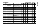
0627 Under-voltage trip mode 0: Disabled, 1: Enabled 0 Disabled / / / 6.25.13
0628 Under-volta
g
e detection time 0.00 10.00 [s] 0.01/0.01 0.03 Disabled / / / 6.25.14
0629 Under-voltage stall level 50 100 [%] 1/0.01 75 Enabled / / / 6.25.15
0630
S
y
stem-supportin
g
sequence
(
B-timer
)
0.0: Invalid, 0.1 10.0 [s] 0.1/0.01 0.0 Enabled / / /
0631 Position deviation limit 0.1 6553 0.1/0.1 16 Disabled /
0632
Brake release inhibition time after run
0.00: Setting of is valid, 0.01 2.50 [s] 0.01/0.01 0.00 Disabled / / /
0633
The trip selection at the VI/II
low-level input
0: Invalid, 1 100 [%] 1/1 0 Enabled / / /
Sensorless vector/vector with sensor ( valid, :invalid)
(*1): Set a time longer than the acceleration/deceleration time.
(
Reference section
)
: Refer to the inverter's individual manual.