


F-25
6.13.4 Dynamic (regenerative) braking - To urgently stop the motor
Dynamic braking mode selection
Dynamic braking resistance
Dynamic braking resistor capacity
[Parameter setting]
Title Function Adjustment range Default setting
Dynamic braking mode selection
: Disabled
: Enabled/overload
detection enabled
Dynamic braking resistance
[ ]
Dynamic braking resistor capacity
[kW]
Model
dependent
Default settings vary from model dependent. Refer to 6.13.4-4).
Protection level is defined by (Refer to 6.13.5).
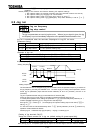
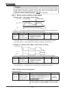
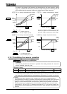
Note 1) While dynamic braking is in operation, “P” blink is displayed at left side of the
monitor. (It is not an error.) The blink starts at achieving (over-voltage
stall protection level / dynamic braking protection level).
Note 2) In the case of oscillating of monitor or taking long time at deceleration, set
(over-voltage stall protection) = .
Note 3) When using braking unit(PB3), set (dynamic braking mode selection) = ,
and (over-voltage stall protection) = .
Note 4) Dynamic braking operates even if the ST-CC terminal is opened.
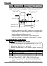
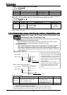
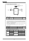
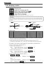
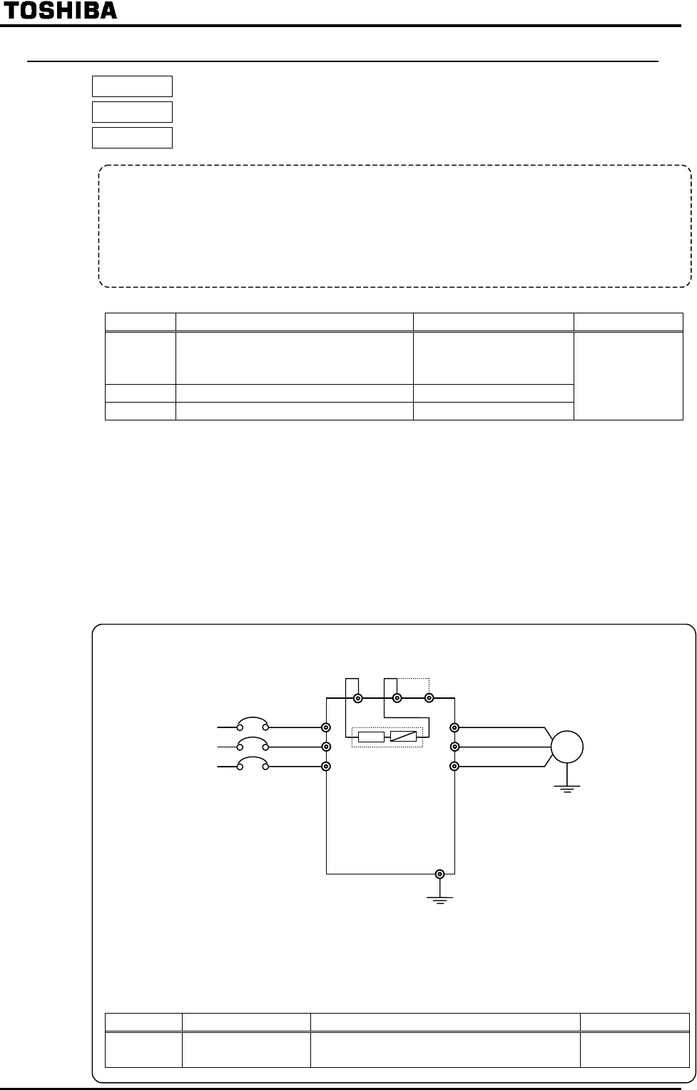
1) An internal braking resistor (for 3.7kW model and smaller)
Note) The internal braking resistor is already connected to terminals PA1 and PB1 (so
that the internal resistor is ready for use). When the internal braking resistor is not
used, change its connection from PB1 to PR1, and also change the setting of the
dynamic braking-related parameter. See 2) on the next page for the connection.
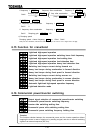
[Parameter setting]
Title Function Adjustment range Setting value
Dynamic braking
mode selection
: Disabled
: Enabled/overload detection enabled
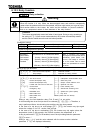
Function
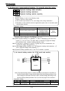
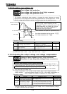
Dynamic braking is used in the following cases:
1) need to stop the motor quickly.
2) The inverter trips because of an over-voltage (OP) during deceleration.
3) Fluctuation of load condition causes a regenerative power even at a constant speed
such as press machine.
Motor
Power
supply
Inverter
Internal braking
resistor
Note)