


F-27
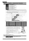
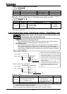
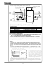
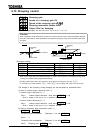
b) When using a braking resistor without thermal fuse
(*1) Connection when using an MCCB with a top coil instead of an MC.
(*2) A step-down transformer is required for 400V models but not for 200V models.
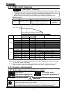
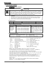
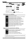
[Parameter setting]
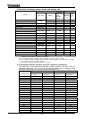
Title Function Adjustment range Setting value
Dynamic braking
mode selection
: Disabled
: Enabled with over load detection
PBR resistor
[ ] Any value (*3)
PBR resistor capacity
[kW] Any value (*3)
(When the standard internal braking resistor option is not used, be sure to set the parameters F308
and F309 properly for overload protection.)
(*3) is for overload protection of our optional PBR and PBR3 type. When DGP type is used,
set = 600 kW and protect the circuit by external thermal.
A thermal relay (THR) must be connected as the last resort for fire prevention in case a failure
occurs in the overload and over-current protective functions provided for the inverter to protect the
braking resistor. Select and connect a thermal relay (THR) with a capacity (watt) commensurate
with that of the braking resistor used.
- Caution -
In the above circuit, the MC in the main circuit is turned off if an inverter's protective function is
activated, and consequently no trip message is displayed. The inverter recovers from a trip if it is
turned off. So, check the trip history record after turning off the inverter and then on again. (Refer
to 8.1.)
To prevent a trip condition from being cleared by turning off the power and then on again,
change the setting of the inverter trip retention selection parameter F602. (Refer to 6.25.3)
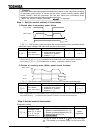
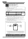
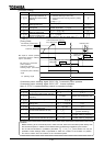
Control power unit option 22kW or less
In a circuit where a control power supply
is connected to RO and SO, when the
MC in the main circuit is turned off when
a trip is occurred, trip data is saved so
that trip messages can be displayed (FL
output also is retained.) For optional
control power supply units, refer to 9.4.
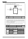
When using a custom braking resistor, be sure to select a braking resistor with a resistance larger
than the minimum admissible resistance. Refer to 4 on the next page for the minimum admissible
resistance.
IM
Motor
External braking resistor
(optional)
Fuse
2:1
(*2)
(*1)
Power
supply
Power
supply
THR
Surge killer
Forward/stop
Reverse/stop
If no power supply is provided
for the control circuit
Inverter
22kW or less
Option