


G-12
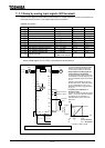
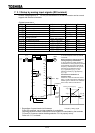
7. 3. 2 Setup by analog input signals (VI/II terminal)
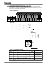
Connect current signal (4 to 20 mADC) to the terminal II or voltage signal (0 to 10 VDC) to the terminal VI
so that the inverter can be run and stopped with external commands.
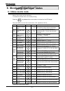
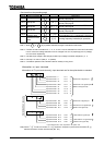
<Related parameters>
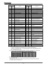
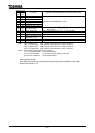
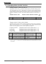
Title Function Adjustment range Default value Setup value
Operation command mode selection (Terminal) (Terminal)
Speed setting mode selection (RR) (VI/II)
FM terminal meter selection
FM terminal meter adjustment
Reference priority selection () ()
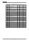
VI/II reference point #1 [%]
VI/II reference point #1 frequency [Hz]
VI/II reference point #2 [%]
VI/II reference point #2 frequency [Hz]
VI/II reference point #1 rate [%]
VI/II reference point #2 rate [%]
Analog input filter
(Disabled) to
(Max. filter capacity)
:Set "" when current signal (4 to 20 mADC) is connected to the terminal II, or set ""
when voltage signal (0 to 10 VDC) is connected to the terminal VI.
M
otor
IM
G/E
R/L1
U/T1
MCCB
Power
su
pp
l
y
S/L2
T/L3
V/T2
W/T3
CC RX
RES
S1
S
2
C
C
S3
S4
F
R
ST
FM
A
M
FP
FLA
FLB
FLC
P24
OUT1
OUT2
VI II RR PP
CHARGE
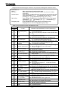
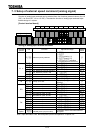
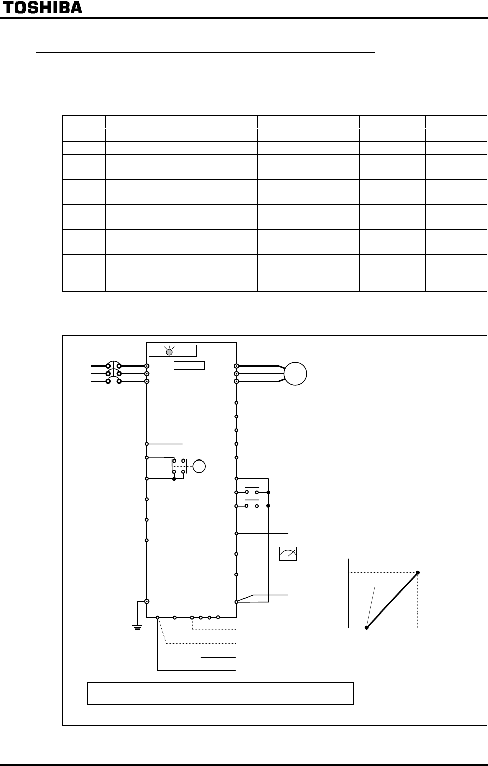
Run/stop setup
To control switching between forward
rotation (F) and reverse rotation (R),
run and stop by external commands.
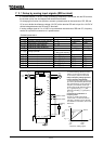
Setup of frequency setting signal and
running frequency characteristic
To set up frequency setting signal and
characteristic of running frequency that
are to be externally input to the terminal
VI or II.
Frequency characteristic is set up at
the two points of VI/II reference point #1
()/frequency(), VI/II
reference point #2() /frequency
().
Connection and calibration of
frequency meter
Connect a 1 mAdc full-scale DC curren
t
meter, 7.5 V dc full-scale DC voltmeter
or rectifier type AC voltmeter. For
calibration of the meter, refer to the
section 5.4.
Forward rotation
Reverse rotation
[Hz]
[%]
Point 2
Point 1
Frequency setting signal
0% 20% 100%
(0 4 20mA)II terminal
(0 10V )VI terminal
Running
frequency
Frequency
meter
The terminals VI and II cannot be used together at a time. Be sure to use either of them.