I-4
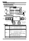
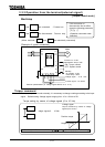
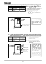
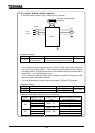
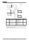
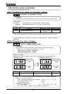
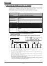
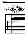
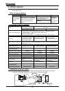
Note on wiring
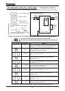
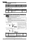
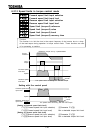
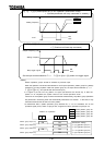
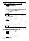
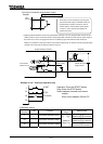
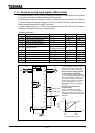
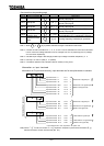
If alternate operation to run and stop the inverter is frequently repeated, don't turn it on/off with
the primary electromagnetic contactor. Run and stop the inverter with the control terminals F
and CC (forward) and R and CC (reverse).
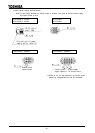
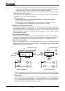
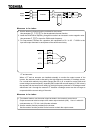
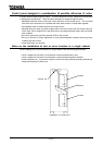
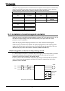
Attach a surge killer to the exciting coil of the electromagnetic contactor (MC)
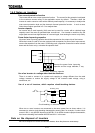
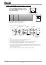
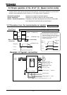
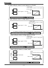
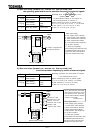
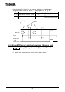
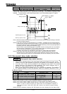
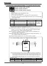
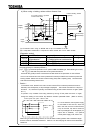
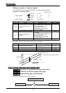
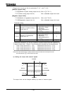
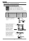
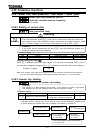
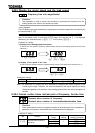
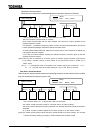
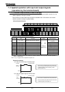
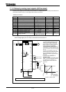
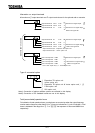
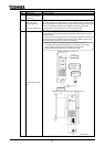
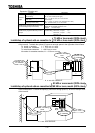
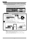
Electromagnetic contactor in the secondary circuit
The secondary electromagnetic contactor can be installed for switching the control motor and
power supply when the inverter is suspended.
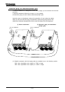
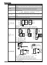
Note on wiring
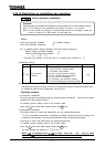
To prevent the commercial power supply from impressing the inverter’s output terminals, be
sure to interlock the secondary electromagnetic contactor with the power supply.
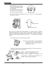
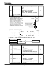
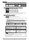
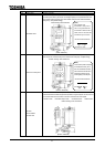
In the case the electromagnetic contactor (MC) is installed between the inverter and motor,
don't turn on/off the electromagnetic contactor on/off while the inverter is running. If the
electromagnetic contactor is turned on/off during operation, it may cause a failure of the
inverter because rush current flows to it.
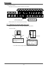
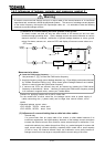
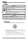
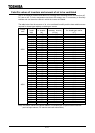
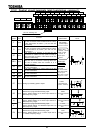
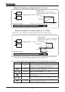
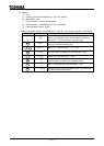
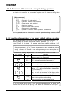
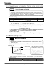
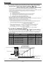
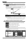
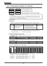
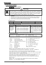
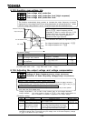
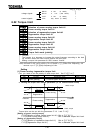
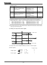
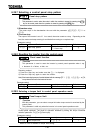
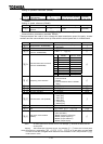
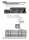
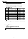
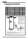
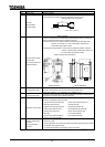
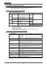
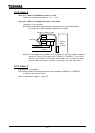
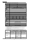
9. 3. Installation of overload relay
The inverter VF-A7 has a built-in electronic thermal overload protection function inside. In
the following cases, however, install an overload relay proper to the electronic thermal
operation level adjustment and motor used between the inverter and motor.
In the case a motor that is different in rated current from Toshiba standard motor is used.
In the case a motor whose output is lower than the specified Toshiba motor of the
standard specifications is independently operated, or two or more units of such the
motors are operated together at a time.
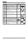
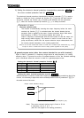
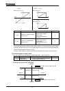
When the low torque motor "Toshiba VF motor" is operated, properly adjust the electronic
thermal protection characteristic of the inverter VF-A7 for the VF motor.
It is recommended to use a motor with motor winding flush type thermal relay in order to
secure motor protection when it runs at low speed.