


B-5
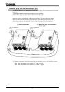
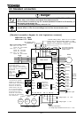
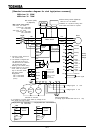
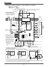
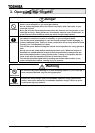
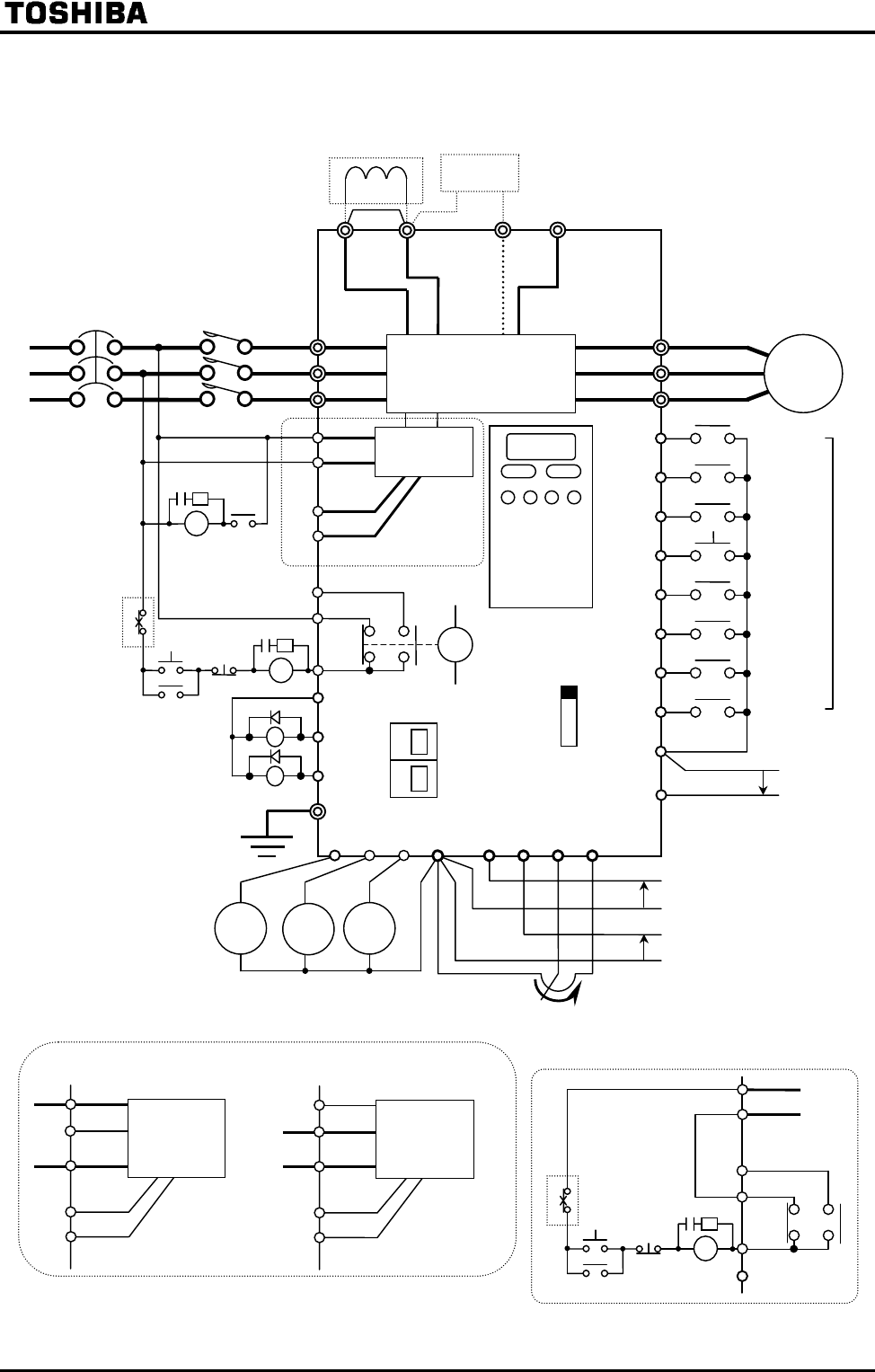
[Standard connection diagram for sink logic(minus common)]
200V class: 75 90kW
400V class: 110 280kW
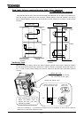
Be sure to attach DC reactor.
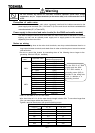
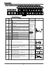
Factory
default
settings
*1:Connect a power source for
the control circuit.
*2:The inverter is shipped with
the terminals PO and PA
shorted with a bar. Remove
this shorting bar and
install a DC reactor (DCL).
*3:Power output for the control
circuit, which is provided
only for the 400V 37kW
and larger models.
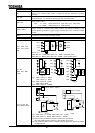
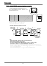
Single-phase
207.5 230V-50/60Hz
(10VA)
Control
circuit
R46
S0
R20
S20
Single-phase 415 440V-50Hz
415
460V-60Hz
R41
Control
circuit
R46
S0
R20
S20
Single-phase 380 415V-50/60Hz
R41
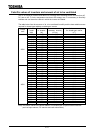
*4: Connections of control power cables by voltage for the
400V 37kW and larger models.
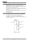
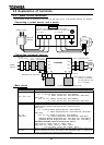
*5: For easy maintenance and inspection, connect the control power terminals RO and SO to the primary side of the MC in the main
circuit so that the control panel can be checked if only the control circuit is energized.
FLC
FLB
FLA
(S20)
Surge suppressor
(R20)
*
Connection of a RUN relay for the 400V models
Main circuit power supply
200V class 75,90kW
3-phase 200 230V-50Hz/60Hz
400V class
110 280kW
3-phese 380 460V-50Hz/60Hz
Control
circuit
Motor
FL
G/E
CC RX
VI
RR
PP
F
RES
CC
R/L1
S/L2
T/L3
U/T1
V/T2
W/T3
Control panel
FLC
FLB
FLA
Voltage signal -10 +10V
Voltage signal 0 10V
Forward
run signal
Preset
speed 1
S1
Preset
speed 4
ST
R
S2
S3
S4
OUT2
P24
OUT1
AMFM
FP
Main circuit
Reverse
run signal
Standby
Reset
Preset
speed 3
Preset
speed 2
Current signal
MCCB
Ammeter
Frequency
meter
Digital
voltmeter
R0
S0
Connector for
common serial
communication
RS485 connector
for serial
communication
Common
External potentiometer
(or voltage signal between RR and CC: 0 10V)
(R20)
(S20)
Voltmeter or ammeter
DC reactor (DCL)
*2 (Optional)
Dynamic braking resistor (Optional)
Refer to 6.13.4 for details
Surge suppressor
b-contact of
overload relay
MC