


E-9
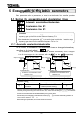
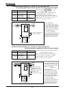
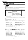
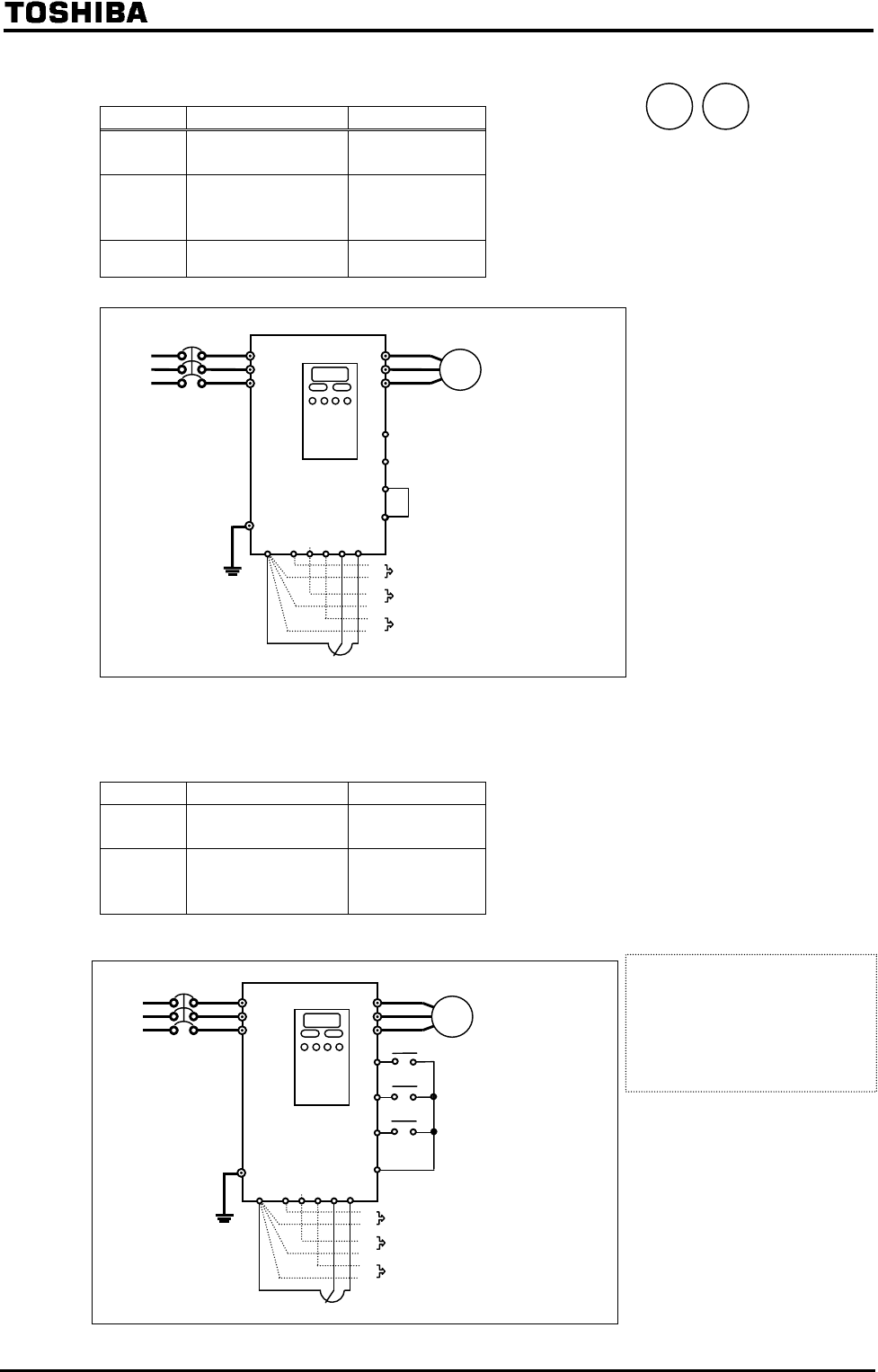
3) Start and stop (forward run, reverse run, free-run stop) with
the operating panel and to set the operation frequency by external signals
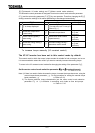
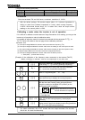
Title Function Set value
Operation command
mode selection
(operating panel)
Speed setting
mode selection
(VI/II)
(RR)
(RX)
Panel stop pattern
(Coast stop)
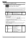
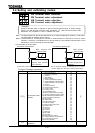
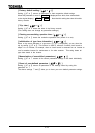
4) Start and stop (forward run, reverse run, free-run stop) and
to set the operation frequency by means of external signals
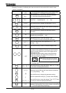
Title Function Set value
Operation command
mode selection
(Terminal input)
Speed setting
mode selection
(VI/II)
(RR)
(RX)
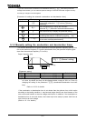
Moto
r
IM
G/E
F
R
ST
R/L1
U/T1
Operating panel
C
C
The inverter is shipped with
these terminals shorted.
Power
supply
S/L2
T/L3
V/T2
W/T3
CC
RX
VI R
R
P
P
External volume control
II
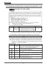
Moto
r
IM
G/E
R/L1
U/T1
Control panel
Power
supply
S/L2
T/L3
V/T2
W/T3
CC RX VI R
R
P
P
External volume control
II
F
R
ST
C
C
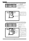
Forward run if ON
Slowdown stop if OFF
Reverse run if ON
Slowdown stop if OFF
Standby if ON
Free-run stop if OFF
A
s for the action the motor takes
when both the terminals F and R
are connected at the same time,
you can make a selection between
reverse run and a stop.
=> Refer to 6.2.2
Other speed setting
: RX2 (voltage input) (optional)
*
: 12/16-bit binary input (optional)*
: Serial communication (optional)*
: Serial communication RS485
: Communication add-on(optional)*
: Up-down frequency
: Pulse input (optional)*
For the setting to be made when using
an asterisked optional device as an
input device, refer to the instruction
manual for the input
device used.
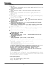
RUN STOP
[Start/stop]: Press the key on the
operating panel.
To switch between forward run and reverse run,
use the forward/reverse run selection .
[Speed command]: By means of external signals
(1) VI: 0 to +10 Vdc (0 to +5 Vdc) II: 4 to 20 mAdc
(2) RR: Volume / 0 to +10 Vdc (0 to +5 Vdc)
(3) RX: 0 to +/-10 Vdc (0 to +/-5 Vdc)
[Start/stop]: Connection and disconnection of terminals
F and CC/terminals R and CC.
[Speed command]: By means of external signals
(1) VI: 0 to +10Vdc (0 to +5Vdc)/II: 4 to 20mAdc
(2) RR: Volume/0 to +10 Vdc (0 to +5Vdc)
(3) RX: 0 to +/-10 Vdc (0 to +/-5Vdc)
Other speed setting
: RX2 (voltage input) (optional)
*
: 12/16-bit binary input (optional)*
: Serial communication (optional)*
: Serial communication RS485
: Communication add-on(optional)*
: Up-down frequency
: Pulse input (optional)*
For the setting to be made when using
an asterisked optional device as an
input device, refer to the instruction
manual for the input
device used.