


I-11
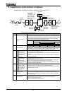
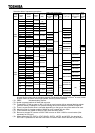
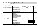
Expansion TB option unit
Function Description
16-bit binary input
(12-bit binary)
4-digit BCD code input (3-digit
BCD code)
Contact
input
Multifunction programmable
input (high-order 8 bits)
Sink input
ON : 5 V DC or less (5 mA type)
OFF : 11 V DC or more, or 0.5 mA or less
Source input
ON : 11 V DC, 2.5 mA or more (maximum 30 V DC)
OFF : 5 V DC or less, or 1.4 mA or less
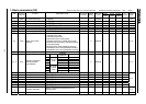
Multifunction programmable analog output
(current/voltage output switchable)
Current: 4 to 20 mA DC output (source output)
Maximum connectable resistance: 750
Voltage: 10 V DC output
Multifunction programmable relay contact
output
1a, 1b contact output (double circuit)
Contact rating : 250 V AC, 2 A (cos = 1)
250 V AC, 1 A (cos = 0.4)
30 V DC, 1 A
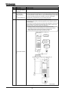
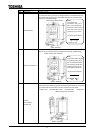
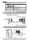
75 kW or less model (200V class)
Installation of optional add-on cassettes to 132 kW or less model (400V class)
To install optional add-on cassette(s), use the attachment and set the options on the right side
of the inverter. To attach the option(s), secure an enough space in the right side of the inverter.
To install a cassette: L = 48.5 mm or more
To install two cassettes: L = 73.5 mm or more
To install three cassettes: L = 98.5 mm or more
No matter for cassettes number, L1 = 33.0 mm or more
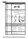
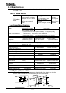
90 kW or more model (200V class)
Installation of optional add-on cassettes to 160 kW or more model (400V class)
To install optional add-on cassette(s), use the attachment and set the options on the right side
of the control panel. To attach the option(s), secure an enough space (L: 50 mm or more) in front
of the inverter.
L
Option cover
Option cover
Flexible connecting
board
Optional add-
on cassettes
LL1
Optional add-
on cassettes
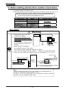
: In a set with SBP001Z.
Attachment
Flexible
connecting
board
Optional add-
on cassettes
: In a set with SBP002Z.