


G-2
7. 2 Applied operation with input and output signals
(operation by the terminal board)
7. 2. 1 Functions of input terminals (in case of sink logic)
Signals that are supplied to control input terminals from the programmable controller, etc. are
used to operate or set up the inverter.
Since function of each contact input terminal is selectable from 136 functions, this inverter
makes it possible to design a system flexibly.
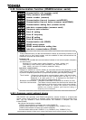
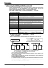
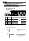
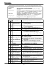
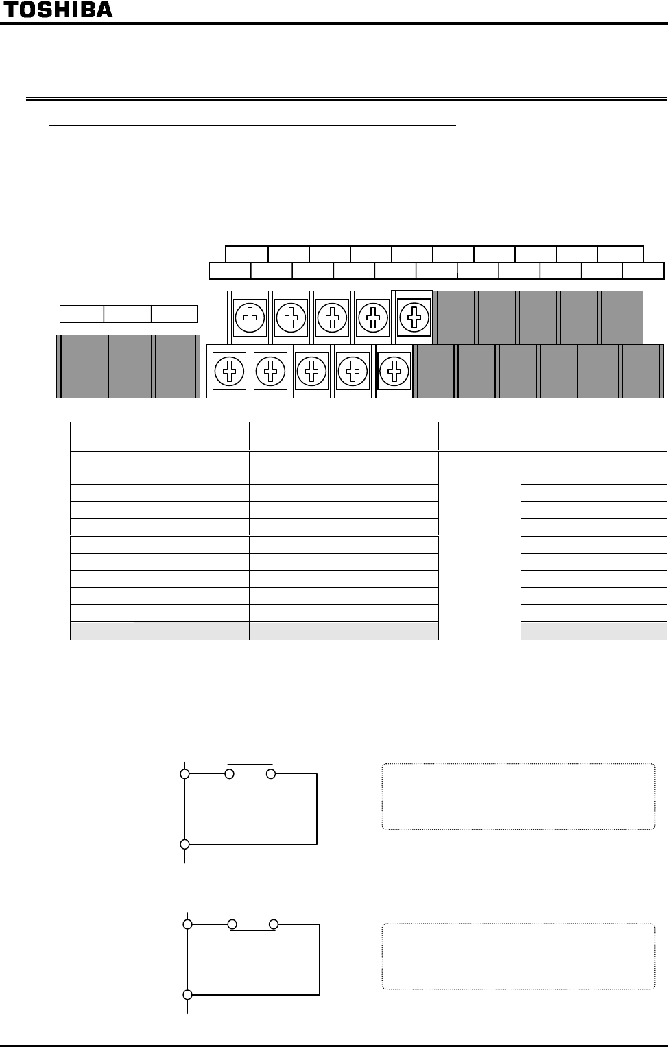
[Control terminal board]
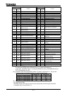
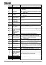
Setting of contact input terminal function
Terminal Title Function
Adjustment
range
Default setting
Always active function selection
(No assignment
function)
F
Input terminal selection #1 (F) (Forward rotation)
R
Input terminal selection #2 (R) (Reverse rotation)
ST
Input terminal selection #3 (ST) (Standby)
RES
Input terminal selection #4 (RES) (Reset)
S1
Input terminal selection #5 (S1) (Preset speed #1)
S2
Input terminal selection #6 (S2) (Preset speed #2)
S3
Input terminal selection #7 (S3) (Preset speed #3)
S4
Input terminal selection #8 (S4) (Preset speed #4)
Option
Input terminal selection #9 #16
(Refer to
page G-4.)
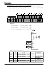
Note:When (Always active function selection) is selected, selected function is generally activated regardless of
positive or negative logic.
Note: is for use of expansion TB option unit.
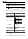
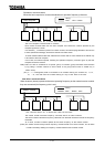
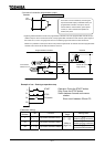
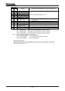
Connection method
1) In case of positive logic (a-contact) input
2) In case of negative logic (b-contact) input
CC
Input
terminal
CC
Input
terminal
This function is activated when the input terminal
and CC (common) are short-circuit, and it is used
for forward rotation, reverse rotation, preset
speed operation, etc.
This function is activated when the input terminal
and CC (common) are open-circuit, and it is used
for standby signal, reset signal, etc.
Inverter
Inverter
a-contact switch
b-contact switch