


I-10
9. 5 Optional add-on cassettes
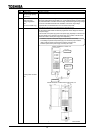
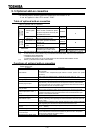
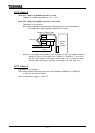
The following add-on cassette options are prepared for the inverter VF-A7.
It can be applied to after CPU version “V300”.
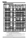
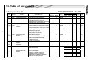
Table of optional add-on cassettes
Table of optional add-on cassettes
Option name Function, purpose Model Remarks (*1)
Vector option
unit
This option compatible to sensor
vector control is usable for speed
control and position control by the
PG feedback function.
VEC001Z
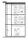
Expansion
terminal
function
Expansion TB
option unit
This option provides extended
terminal functions for use.
ETB001Z
A
S20 option unit
This option provides TOSLINE-
S20 for use.
TLS001Z
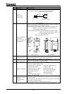
Commun
ication
function
F10M option
unit
This option provides TOSLINE-
F10 for use
TLF001Z
B
SBP001Z For 75(132) kW or less(*3)
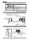
Attachment
Attachment for fitting add-on
cassette option to the inverter.
SBP002Z For 90(160) kW or more(*3)
(*1): One can use two of Group A together with one of the Group B at a time. (Maximally 3 options)
(*2): To use 37 kW or more models in any of conditions described below, refer to 9.7 and execute the
preparation before attachment.
i ) install the vector option unit
ii) install the S20 option unit or the F10M option unit and execute PG feedback control
(*3): Inside ( ) indicates case of 400V class models.
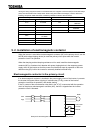
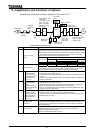
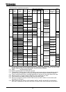
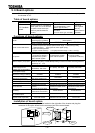
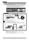
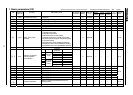
Functions of optional add-on cassettes
Vector option unit
Function Description
PG feedback
Consistent with line driver output encoder (Disconnection detection function is
also provided)
Consistent with complementary/open-collector encoder (Pulse train speed
command)
Max. pulse freq. 60kHz(2-phase), 120kHz(single-phase), Duty: 50 10%
Power supply for encoder 5 V, 6 V, 12 V, 15 V DC, 160 mA or less
Voltage drop detection Detection of voltage drop in PG power supply line
Standby signal output
Open-collector output/sink output (30 V DC, 50 mA or less)
Approximately 1 second after the main circuit power is turned on, this terminal is
connected with COM. In an error status, circuit between this terminal and COM is
open regardless of main circuit power supply.
OC pre-alarm
Open-collector output/sink output (30 V DC, 50 mA or less)
When current exceeds the limiting range, this terminal is connected with COM.
Alarm output (Error code 0, 1,
2, 3)
With occurrence of an error, the cause of trip is output in 4-bit binary system. Error
is detected according to the open/closed status of the circuit between the open-
collector of each terminal and COM.
P24 power supply +24 V DC power supply (200 mA or less) for driving external relay, etc.
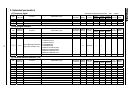
PG feedback output
Open-collector outputs of phase-A positioning pulse, phase-B positioning pulse,
phase-Z positioning pulse originating from the encoder built in the motor. (30 V DC,
50 mA or less)
PG line driver output
Outputs phase-A positioning pulse, phase-B positioning pulse, phase-Z positioning
pulse originating from the line drive output encoder built in the motor.
10 V analog command power
supply
Power supply for 10 V analog voltage command. (Internal impedance: 500 ,
for 1 k resistor)
10 V analog command input 10 V programmable voltage command is input to this terminal.
Pulse train position control
command input
Pulse train positioning commands for forward rotation and reverse rotation are
input to this terminal. This terminal is enabled only when it is set in the position
control mode or switched for position control.
Encoder supply voltage check To check encoder supply voltage.