


L-2
(Continued from the preceding page)
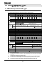
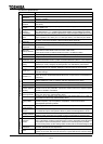
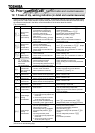
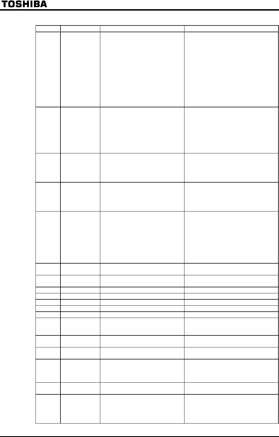
Indication
Contents Expected causes
Countermeasures
Over-voltage
during fixed
speed
Input voltage abnormally varied.
1 Power capacity is 500 kVA or
more.
2 Power-factor improving
capacitor was turned on/off.
3 Some unit using thyrister is
connected with the same
power supply line.
Motor falls into regeneration status
because it is rotated fast
exceeding inverter's output
frequency by power of loaded
side.
Try to insert input reactor.
Install dynamic braking resistor.
Inverter
overloaded
Rapid acceleration is operated.
DC breaking rate is too high.
V/f parameter is improperly set.
Running motor is started during
momentary power failure status
or so.
Load is too heavy.
Extend acceleration time #1 .
Decrease values of DC injection
braking current and DC
injection braking time .
Check V/f parameter.
Use (Auto-restart) and
(
Regenerative power ride-through control
).
Raise rating of the inverter.
Motor
overloaded
V/f parameter is improperly set.
Motor is locked.
Continuous operation in low
speed range.
Motor is operated with overload.
Check V/f parameter.
Check loading unit.
Reset properly to motor's
overload reduction start-up
frequency.
Dynamic braking
resistor overload
Rapid deceleration is operated.
Dynamic braking rate is too high.
Set over-voltage limit operation
revel parameter too small.
Extend deceleration time #1 .
Increase capacity (wattage) of
dynamic braking resistor and reset
the PBR capacity parameter .
Increase the setting value of .
Overheat
Cooling fan is not actuated.
Ambient temperature is too high.
Vent of cooling fan is shut.
Some heat generating matter is
located nearby.
Internal thermistor of unit is
disconnected.
After cooling down inverter, reset it
from failure and try to restart it.
If cooling fan does not work in
operation, it needs replacement.
Secure spaces in the periphery of the
inverter.
Don't locate any heat generating thing
near the inverter.
Make a service call.
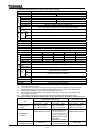
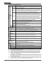
Emergency
stop
Inverter is stopped by panel operation
during automatic or remote operation.
Reset the inverter.
EEPROM error
Error occurs during writing data. Again turn on the inverter. If it is not
reset, make a service call.
Initial read-error
Something abnormal in internal data.
Make a service call.
Initial read-error
Something abnormal in internal data.
Make a service call.
Main RAM fault
Something abnormal in control RAM.
Make a service call.
Main ROM fault
Something abnormal in control
ROM.
Make a service call.
CPU
fault
Something abnormal in control CPU.
Make a service call.
Interruption
communication
fault
Something abnormal occurred
during communication operation.
Check communication units and their
connections.
Gate array
fault
Main gate array is abnormal. Make a service call.
Output current
detector error
Main output current detector is
abnormal.
Make a service call.
Optional unit
fault
Something abnormal occurred in
some optional unit (including
abnormal communication [optional
add-on cassettes]).
Check connection of optional
board(s).
Refer to instructions of options
concerned.
Flush memory
fault
Something abnormal in flush
memory.
Make a service call.
(*1)
low-current
operation
Output current declined to the
low-current detection level during
operation.
Check to see if low-current detection
level is set properly to the system or
not ().
If low-current detection level is
properly set, make a service call.
(Continued on the following page)