


B-3
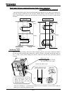
2.2 Standard connection
Danger
Prohibited
-Do not connect the power cables to any output terminal (U/T1, V/T2 or W/T3 on the
motor side), or the inverter could break down and cause a fire.
-Do not connect a resistor to any D.C. terminal (between PA and PC or PO and PC), or
the inverter could cause a fire.
To install external braking resistor, refer to 6.13.4.
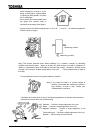
Be Grounded
-Connect grounding wires correctly and securely. Failure to do so could cause an
electric shock or a fire if current leakage occurs or the inverter breaks down.
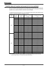
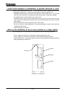
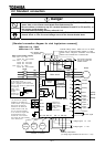
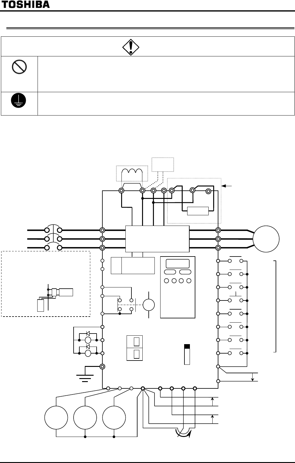
[Standard connection diagram for sink logic(minus common)]
200V class: 0.4 22kW
400V class: 0.75 22kW
Main circuit power suppl
y
200V class 0.4 7.5kW
3-phase 200 230V-50/60Hz
200V class 11 22kW
3-phase 200 220V-50Hz
3-phase 200 230V-60Hz
400V class 0.75 22kW
3-phase 380 460V-50/60Hz
Control
circuit
Motor
FL
G/E
CC RX
VI
RR PP
F
RES
CC
R/L1
S/L2
T/L3
U/T1
V/T2
W/T3
Control panel
FLC
FLB
FLA
External potentiometer
(or voltage signal between RR and CC: 0 10V)
Voltage signal -10 +10V
Voltage signal 0 10V
Forward
Preset
speed 1
S1
Preset
speed 4
ST
R
S2
S3
S4OUT2
P24
OUT1
AMFM
FP
A
mmete
r
Frequency
meter
Digital
voltmeter
Main circuit
Built-in dynamic braking resistor
Reverse
Standb
y
Reset
Preset
speed 3
Preset
speed 2
Current signal
MCCB
Voltmeter or ammeter
R0
S0
This circuit is provided
only for the 3.7kW and
smaller models.
Connector for
common serial
communication
RS485 connector
for serial
communication
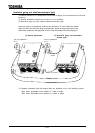
SINK
SOURCE
Common
CN21
*
When using a separate power source
for the control circuit
For the 22kW and smaller models,
power is supplied to the control circuit
from the main circuit.
An optional device
is required to
supply from
another source.
(though
terminals only
are provided.)
CN21
Control circuit
DC reactor (DCL)
*2 (Optional)
*1: The control power supply terminals
RO and SO are optionally
available for the 22kW and
smaller models. Though terminals
RO and SO are fitted as
standard for the 22kW and
smaller models as well, they
are not connected internally.
*2: The inverter is shipped with
the terminals PO and PA
shorted with a bar. Remove
this shorting bar when installing
a DC reactor (DCL).
Option
Factory
default
settings
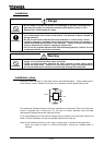
External braking resistor Refer to 6.13.4 for details
When using an external braking resistor in 3.7kW
model or less,
change the connection of the internal
resistor from terminal PB1 to terminal PR1.