


F-17
[Parameter setting]
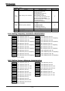
Title Function Adjustment range Default setting
Motor shaft fixing control : Disabled, : Enabled
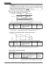
If the motor shaft fixing control parameter is set at , DC braking continue at half a
braking rate of that set with to retain the motor after it has come to a full stop by DC
braking. To terminate the motor shaft fixing control, cut off the standby signal (ST signal).
Note 1) Almost the same motor shaft fixing control can be exercised when DC injection braking is controlled
by means of external signals.
Note 2) If the motor shaft fixing control parameter is set at (enabled) when the output frequency
is below the DC injection braking start frequency and terminals ST-CC are closed (ON), the
DC injection braking function is activated and the motor shaft fixing control continues regardless of
the setting of the D.C. braking time parameter .
However, when a general-purpose motor is operated, if the D.C. braking rate is set above
60% and the D.C. braking time is set at a certain value, the overload protective function
may be activated by the electronic thermal protective function.
In addition, the inverter may automatically control the D.C. braking rate to avoid tripping.
Note 3) If the motor shaft is set free because of a power failure, the brake shaft fixing control is
discontinued. Also, if the inverter trips when the motor shaft fixing function is active, the fixing
control is discontinued, whether or not it automatically recovers from tripping by its retry function.
6.8.3 Zero-speed stop mode selection
Zero-speed stop mode selection
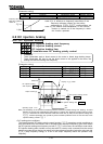
[Parameter setting]
Title Function Adjustment range Default setting
Zero-speed stop mode selection
:
Standard(DC injection braking)
: 0 Hz command
DC injection braking start frequency
[Hz]
DC injection braking time
[s]
Note.1) This function doesn't operate when = .
Note.2) If this function is set up, motor shaft fixing control()cannot be used.
Note.3) This function doesn't operate at the time of a torque control and position control.
Note.4) This function doesn't operate except the time of the vector control (= , ) with a
sensor. In order to use this function, the option board for PG feedback is required. In
other than the vector control (= , ) with a sensor, the usual DC injection braking
operates.
Note.5) Since the reference frequency that will suspend the motor abruptly from the state of high
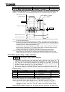
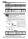
[s]
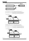
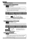
Output frequency [Hz]
LED display lights
Operating signal (F-CC)
ON
OFF
Output current [A]
0
0
Setting frequency
Stand-by signal (ST-CC)
ON
OFF
2
lights
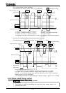
Function
This function controls motor in the zero-speed state at the time of a stop. If this
function is set up, 0Hz reference will be put out instead of DC braking at the time
of a stop, and a motor will be controlled in the setting time stop state. The monitor
display serves as during this control operation. This function operates only at
the time of vector control (= , ) with a sensor.
Refer to the direct-current braking (6.8.1) for conditions of operation. The portion of
DC injection braking is served as operation which set frequency reference to 0Hz.