


J-12
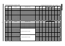
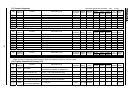
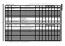
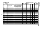
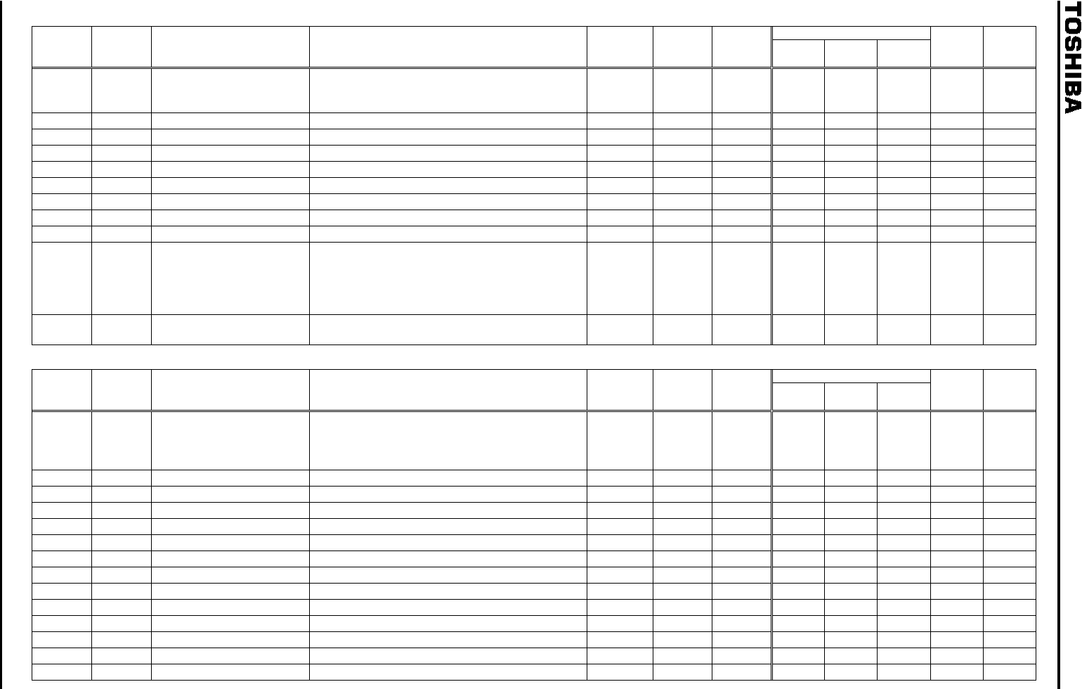
[22] Motor constant
Vector control
Title
Communi
cation No
Function Adjustment range
Min. unit (panel/
communication)
Default
setting
Write during
running
Speed
control
To rque
control
Position
control
V/f
Constant
Reference
section
0400 Auto-tuning
0:Without auto-tuning (internal table)
1:Motor constant initialization (0 after execution)
2:Automatic tuning execution (0 after execution)
0 Disabled / / / 6.20
0401 Slip frequency gain 0.00 2.55 0.01/0.01 0.60 Enabled / / 6.20
0402
Motor constant #1 (primary resistance)
0.00 100000 [ ] (*1) 0.01/0.01* See J-28 Disabled / / / 6.20
0403
Motor constant #2 (secondary resistance)
0.00 100000 [ ] (*1) 0.01/0.01* See J-28 Disabled / / / 6.20
0404
Motor constant #3 (exciting inductance)
0.0 6500 [mH] 0.1/0.1 See J-28 Disabled / / / 6.20
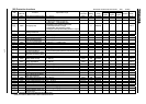
0405
Motor constant #4 (load inertia moment)
0.0 100.0 0.1/0.1 1.0 Enabled / / / 6.20
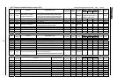
0410
Motor constant #5 (leak inductance)
0.00 650. 0 [mH] 0.01/0.01 See J-28 Disabled / / / 6.20
0411 Number of motor poles 2, 4, 6, 8, 10, 12, 14, 16 1/1 4 Disabled / / / 6.20
0412 Rated capacity of motor 0.10 [Model Dependent] 0.01/0.01 See J-28 Disabled / / / 6.20
0413 Motor type
0: Toshiba standard motor #1
1: Toshiba VF motor
2: Toshiba V3 motor
3: Toshiba standard motor #2
4: Other motors
0 Disabled / / / 6.20
0414 Auto-tuning prohibition
0: Prohibited 1: Valid for sensorless vector
2: Valid for vector with PG
1 Disabled / / / 6.20
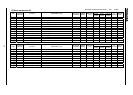
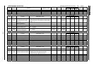
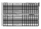
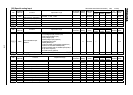
[23] Torque control
Vector control
Title
Communi
cation No
Function Adjustment range
Min. unit (panel/
communication)
Default
setting
Write during
running
Speed
control
To rque
control
Position
control
V/f
Constant
Reference
section
0420 Torque reference selection
1: VI/II, 2: RR, 3: RX, 4: RX2(optional), 5: Panel input,
6: Binary/BCD input(optional), 7: Common serial
communication option, 8: Serial communication RS485,
9: Communication add-on cassette option
3Enabled / 6.21.1
0421 Torque reference filter 10.0 199.9, 200.0(without filter) 0.1/0.1 200.0 Enabled / / 6.21.2
0422
Selection of synchronized torque bias input
0: Invalid, 1 to 9 (Same as ) 0Enabled/ / 6.21.4
0423
Selection of tension torque bias input
0: Invalid, 1 to 9 (Same as ) 0Enabled / 6.21.4
0424
Load sharing gain input selection
0: Invalid, 1 to 9 (Same as ) 0Enabled / 6.21.4
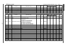
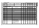
0425
Forward speed limit input selection
0: Invalid, 1: VI/II, 2: RR, 3: RX, 4: RX2(optional), 5:
0Enabled / / 6.21.3
0426
Forward speed limit input level
0.0 [Hz] 0.01/0.01 80.0 Enabled / / 6.21.3
0427
Reverse speed limit input selection
0: Invalid, 1: VI/II, 2: RR, 3: RX, 4: RX2(optional), 5:
0Enabled / / 6.21.3
0428
Reverse speed limit input level
0.0 [Hz] 0.01/0.01 80.0 Enabled / / 6.21.3
0429
Torque reference mode selection
0: Fixed direction, 1:F/R permitted 0 Disabled / 3.3.2
0430
Speed limit (torque 0) reference 0: Invalid, 1: VI/II, 2: RR, 3: RX, 4: RX2(optional), 5:
0Enabled / 6.21.3
0431 Speed limit(torque 0) level 0.0 [Hz] 0.01/0.01 0.0 Enabled / 6.21.3
0432 Speed limit(torque 0) band 0.0 [Hz] 0.01/0.01 0.0 Enabled / 6.21.3
0433
Speed limit(torque 0) recovery time
0.00 2.50 0.01/0.01 0.20 Disabled / 6.21.3
* To be dealt as an index in case of 16-bit access. Sensorless vector/vector with sensor :valid :invalid
When adjustment value is 10 (10000m ) or more, 1000(in case of 10000m ) and blink alternately.
When adjustment value is 100 (10000m ), 1000 and blink alternately.