


109
4
PARAMETERS
Position control
4.5.9 Setting the position adjustment parameters (Pr.426, Pr.506, Pr.507, Pr.510, Pr.511,
Pr.536, Y36 signal, PBSY signal, MEND signal, CPO signal, FP signal)
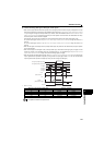
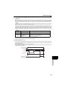
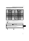
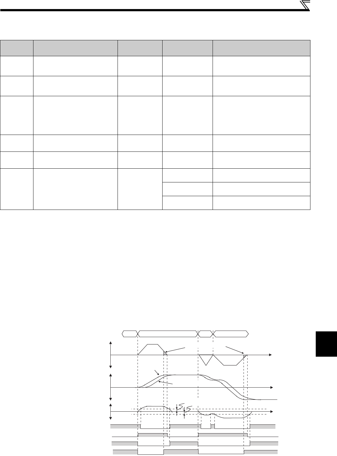
(1) In-position width and in-position signal (Pr.426, Y36 signal)
If the number of droop pulses [after the electronic gear] (= position command [after the electronic gear] - current position
[after the electronic gear]) falls below the setting of Pr.426 In-position width, the in-position signal (Y36 signal) is turned
ON. For the in-position signal (Y36 signal), assign the function by setting "36 (positive logic) or 136 (negative logic)" in
any of Pr.190 to Pr.192 (output terminal function selection).
(2) Position command creating signal (PBSY signal)
The position command creating signal (PBSY signal) is turned ON while a position command is being created. For the
terminal used for the position command creating signal (PBSY), assign the function by setting "61 (positive logic)" or "161
(negative logic)" in any of Pr.190 to Pr.192 (output terminal function selection).
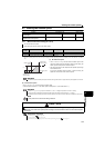
The drive unit has three output terminals at the maximum.
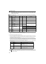
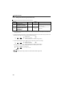
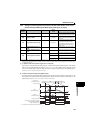
Parameter
number
Name Initial value
Setting
range
Description
426 In-position width
100 pulses 0 to 32767 pulses
When the number of droop pulses [after
the electronic gear] falls below the setting,
the in-position signal (Y36) is turned ON.
506
Position detection
hysteresis width
0 0 to 32767
Set the hysteresis width for the detection
position of the position detected signal
(FP signal).
507 Rough match output range
0 0 to 32767
Set the remaining command distance
[before the electronic gear] (= target
position [before the electronic gear] -
current position [before the electronic
gear]) at which the rough match signal
(CPO) is output.
510
Position detection lower 4
digits
0 0 to 9999
Set the lower four digits of the position
detection value.
511
Position detection upper 4
digits
0 0 to 9999
Set the upper four digits of the position
detection value.
536 Position detection selection
0
0
The position is detected on both the plus
and minus sides.
1
The position is detected on the plus side
only.
2
The position is detected on the minus side
only.
The above parameters can be set when Pr.160 Extended function display selection = "0". (Refer to page 182)
With the operation panel of the drive unit, up to "9999" can be set as a setting value. With a parameter unit or FR configurator, up to the highest value in
the setting range can be set.
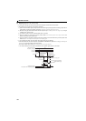
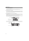
ON ON
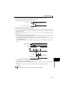
ON
ON
ON
ONON
ON ON
ON
ON
Speed command
0
Position
[before electronic gear]
Target position
[before electronic gear]
0
Droop pulse
[after electronic gear]
0
Position command creating signal (PBSY)
In-position signal (Y36)
Travel completed signal (MEND)
Rough match signal (CPO)
0 1000 500 -1000
Pr.507 Rough match output range
Position
command
Time
Time
Pr.426 In-position width
Current position