


150
Function assignment of external terminal and control
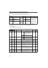
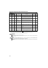
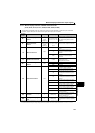
4.12.7 Output current detection function (Y12 signal, Y13 signal, Pr.150 to Pr.153)
The above parameters can be set when Pr.160 Extended function display selection = "0". (Refer to page 182)
The output current during drive unit running can be detected and output to the output terminal.
Parameter
number
Name Initial value
Setting
range
Description
150
Output current detection
level
150% 0 to 200% 100% is the rated drive unit current.
151
Output current detection
signal delay time
0s 0 to 10s
Output current detection period.
The time from when the output current has risen
above the setting until the output current
detection signal (Y12) is output.
152
Zero current detection
level
5% 0 to 200%
The rated drive unit current is assumed to be
100%.
153
Zero current detection
time
0.5s 0 to 1s
Period from when the output current drops below
the Pr.152 value until the zero current detection
signal (Y13) is output.
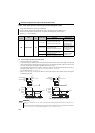
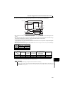
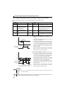
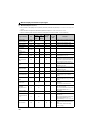
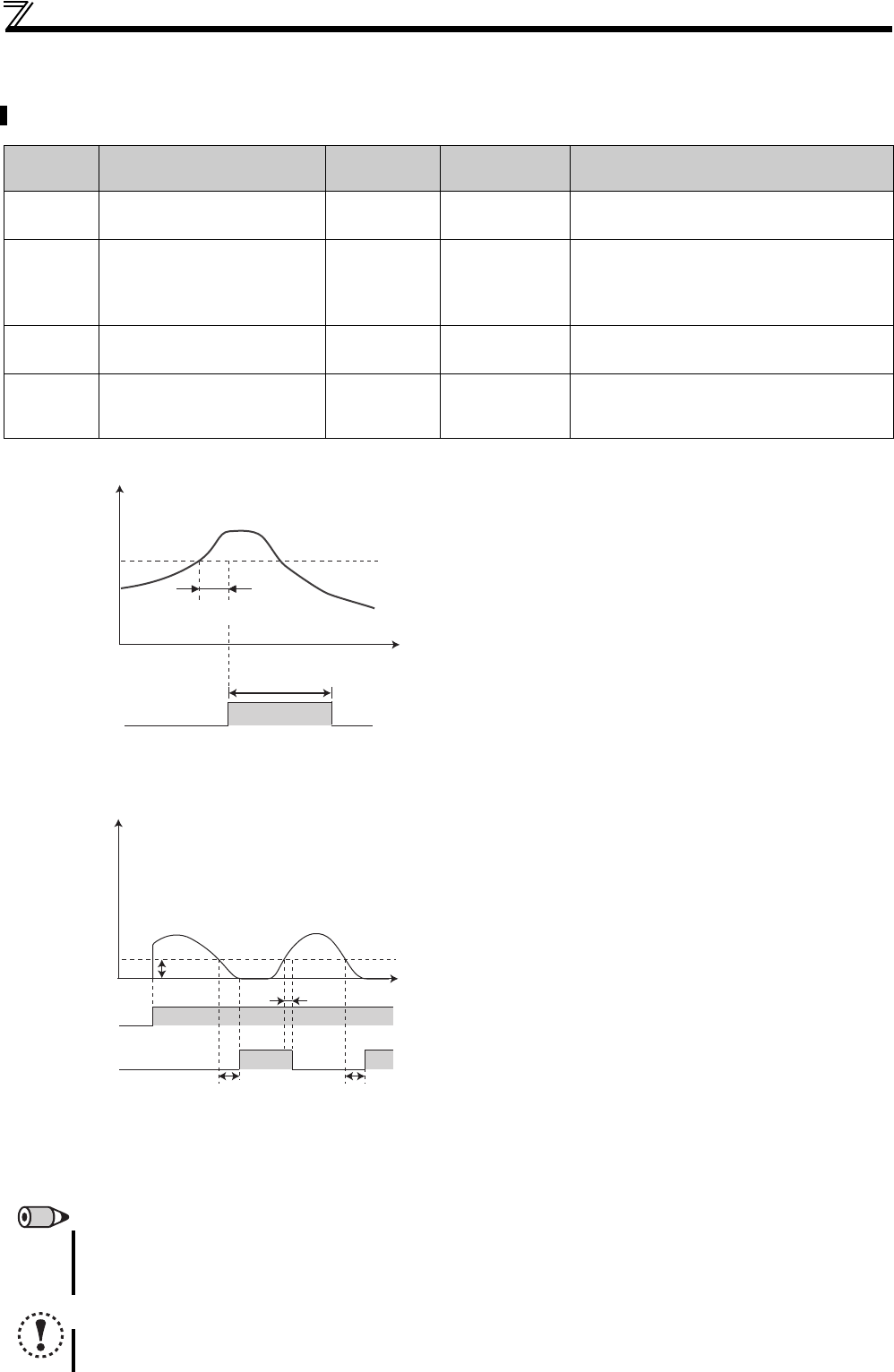
(1) Output current detection (Y12 signal, Pr.150,
Pr.151)
The output current detection function can be used for
excessive torque detection, etc.
If the output current remains at the Pr.150 setting or higher
during drive unit operation for longer than the time set in
Pr.151, the output current detection signal (Y12) is output
from the drive unit's open collector or relay output terminal.
When the Y12 signal turns ON, the ON state is held for
approximately 100ms.
For the Y12 signal, set "12 (positive logic) or 112 (negative
logic)" in Pr.190 to Pr.192 (output terminal function selection)
and assign functions to the output terminal.
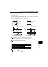
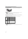
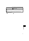
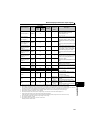
(2) Zero current detection (Y13 signal, Pr.152, Pr.153)
If the output current remains at the Pr.152 setting or lower
during drive unit operation for longer than the time set in
Pr.153, the zero current detection (Y13) signal is output from
the drive unit's open collector or relay output terminal.
When the drive unit's output current falls to "0", torque will
not be generated. This may cause a drop due to gravity
when the drive unit is used in vertical lift application.
To prevent this, the Y13 signal can be output from the drive
unit to close the mechanical brake when the output current
has fallen to "zero".
For the Y13 signal, set "13 (positive logic) or 113 (negative
logic)" in Pr.190 to Pr.192 (output terminal function selection)
and assign functions to the output terminal.
REMARKS
The response time of Y12 and Y13 signals is approximately 0.1s. Note that the response time changes according to the load
condition.
When Pr.152 = "0", detection is disabled.
NOTE
Changing the terminal assignment using Pr.190 to Pr.192 (output terminal function selection) may affect the other
functions. Set parameters after confirming the function of each terminal.
Time
Pr.150
OFF
ON
OFF
Output current
detection signal
(Y12)
100ms
Output current
Pr.151
OFF ON
Start signal
Time
Output current
OFF
ON
Zero current
detection time
(Y13)
Pr.153
Detection time
Pr.153
Detection time
Pr.152
OFF
ON
0[A]
100ms∗
Pr.152
The zero current detection signal (Y13) holds the
signal for approximately 100ms once turned ON.