


213
Communication operation and setting
4
PARAMETERS
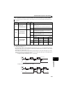
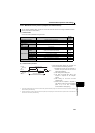
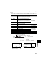
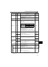
7) Error code
If any error is found in the data received by the drive unit, its definition is sent back to the computer together with the
NAK code.
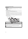
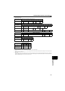
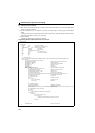
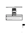
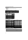
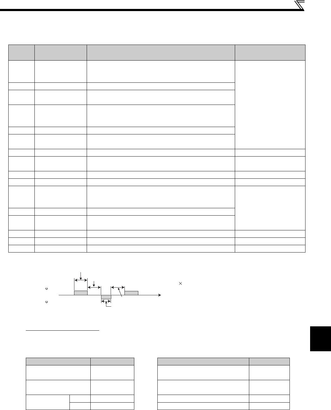
(5) Response time
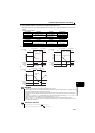
[Formula for data sending time]
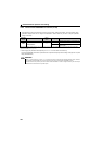
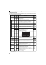
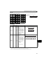
Communication specifications Data check time
Error
Code
Error Item Error Description Drive Unit Operation
H0 Computer NAK error
The number of errors consecutively detected in communication
request data from the computer is greater than allowed number of
retries.
Brought to trip (E. PUE) if
error occurs continuously
more than the allowable
number of retry times.
H1 Parity error The parity check result does not match the specified parity
H2 Sum check error
The sum check code in the computer does not match that of the
data received by the drive unit.
H3 Protocol error
The data received by the drive unit has a grammatical mistake.
Alternatively, data receive is not completed within the
predetermined time. CR or LF is not as set in the parameter.
H4 Framing error The stop bit length differs from the initial setting.
H5 Overrun error
New data has been sent by the computer before the drive unit
completes receiving the preceding data.
H6
H7 Character error
The character received is invalid (other than 0 to 9, A to F, control
code).
Does not accept received
data but is not brought to trip.
H8
H9
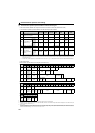
HA Mode error
Parameter write was attempted in other than the computer link
operation mode, when operation command source is not selected
or during drive unit operation. Does not accept received
data but is not brought to trip.HB Instruction code error The specified command does not exist.
HC Data range error
Invalid data has been specified for parameter write, speed setting,
etc.
HD
HE
HF
1
Number of data characters
(Refer to page 210)
Communication
(Total number of bits) = data send time (s)
(Refer to the following.)
Communication speed (bps)
Name Number of Bits Item Check Time
Stop bit length
1 bit
2 bits
Various monitors, operation command,
speed setting (RAM)
< 12ms
Data length
7 bits
8 bits
Parameter read/write, speed setting
(EEPROM)
< 30ms
Parity check
Present 1 bit Parameter clear/all clear < 5s
Absent 0 Reset command No answer
In addition to the above, 1 start bit is necessary.
Minimum number of total bits.................9 bits
Maximum number of total bits................12 bits
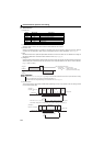
10ms or more necessary
Computer
Drive unit
Drive unit
Computer
Data sending time (refer to the following formula)
(Setting 10ms)
(depends on the instruction
code (see the following table))
Drive unit data processing time = waiting time + Data check time
Data sending time (refer to the following formula)
Time