


202
Communication operation and setting
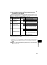
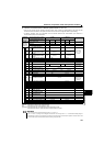
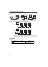
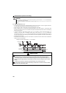
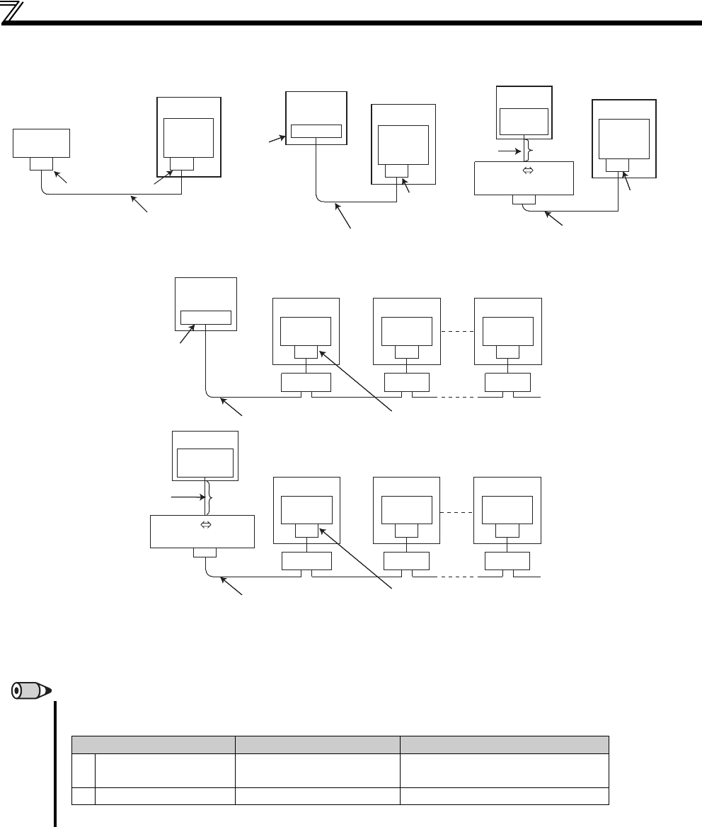
(2) PU connector communication system configuration
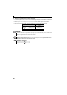
Connection of a computer to the drive unit (1:1 connection)
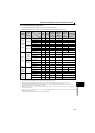
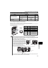
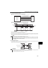
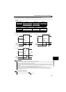
Combination of a computer and multiple drive units (1:n connection)
REMARKS
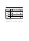
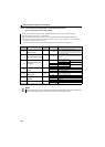
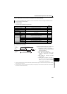
Refer to the following when fabricating the cable on the user side.
Examples of product available on the market (as of February 2012)
Do not use pins No. 2, 8 of the communication cable. (Refer to page 201)
PU
connector
Drive unit
Station 0
Computer
RS-485
interface/terminals
Communication cable 1)
RJ-45
connector 2)
PU
connector
Drive unit
FR-PU07
Communication cable 1)
RJ-45 connector 2)
PU
connector
Drive unit
Station 0
Computer
Communication cable 1)
RJ-45
connector 2)
RS-232C
connector
RS-232C RS-485
converter
RS-232C
cable
Maximum
15m
Computer
Terminating resistor∗
RS-232C
connector
RS-232C
cable
Maximum
15m
Drive unit
Staion 0
Computer
Terminating resistor∗
PU
connector
PU
connector
PU
connector
PU
connector
PU
connector
PU
connector
Communication cable 1)
Distributor
RJ-45connector 2)
3)
Drive unit
Staion 1
Drive unit
Staion n
(max. 32 drive units)
Drive unit
Staion 1
Distributor
3)
Drive unit
Staion 2
Drive unit
Staion n
Communication cable 1)
RJ-45connector 2)
RS-485
interface/terminals
RS-232C RS-485
converter
The drive units may be affected by reflection depending on the transmission speed or transmission distance. If this reflection
hinders communication, provide a terminating resistor. If the PU connector is used to make a connection, use a distributor since a
terminating resistor cannot be fitted. Connect the terminating resistor to only the drive unit remotest from the computer.
(Terminating resistor: 100)
Product Type Maker
1) Communication cable
SGLPEV-T (Cat5e/300m)
24AWG 4P
Mitsubishi Cable Industries, Ltd.
2) RJ-45 connector 5-554720-3 Tyco Electronics Corporation