


147
Function assignment of external terminal and control
4
PARAMETERS
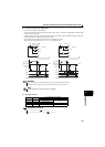
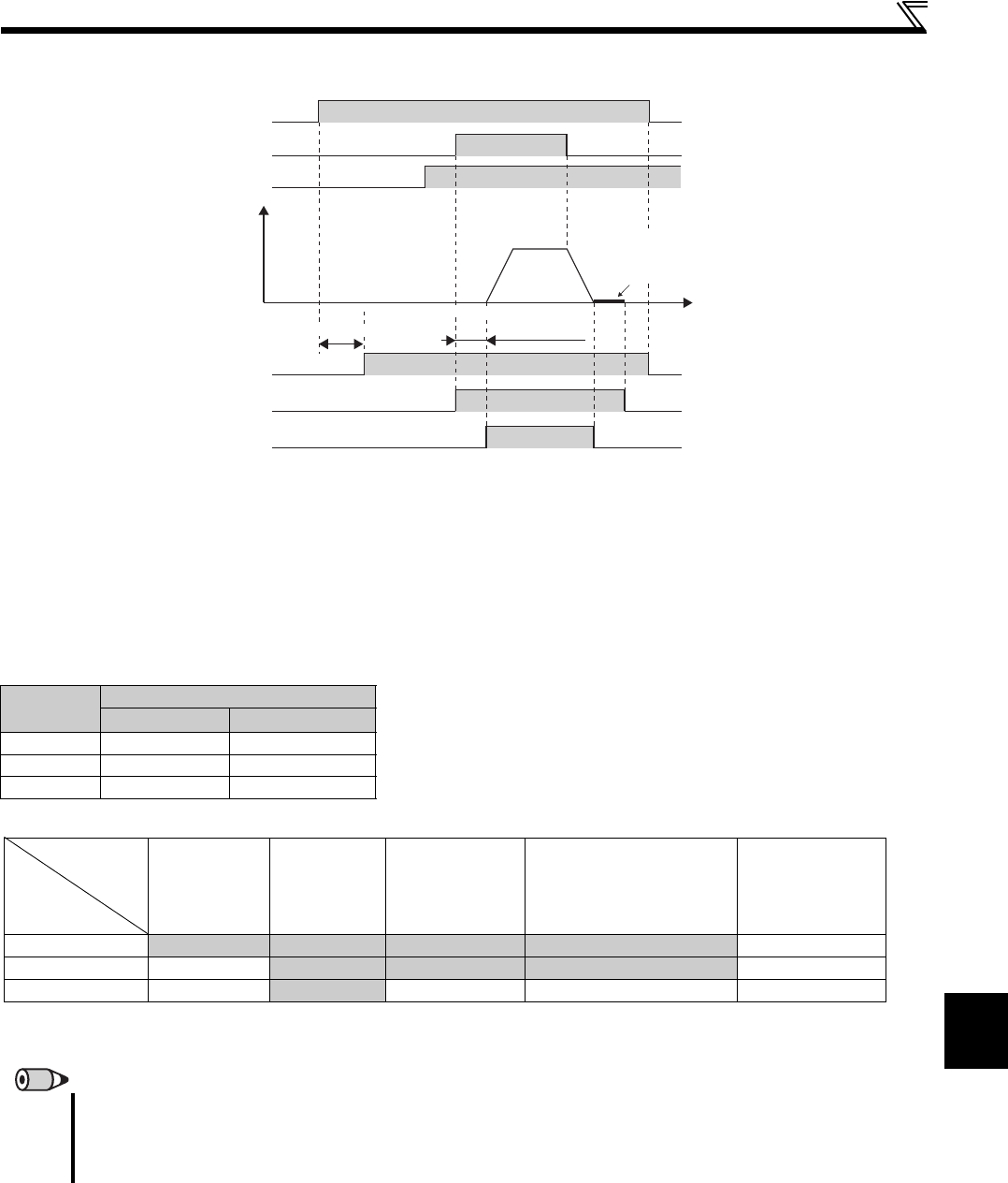
(2) Drive unit operation ready signal (RY signal) and drive unit running signal (RUN signal)
When the drive unit is ready to operate, the output of the operation ready signal (RY) is ON. (It is also ON during drive unit
running.)
When the output speed of the drive unit rises to or above 1r/min, the drive unit running signal (RUN) is turned ON. During a
drive unit stop, zero speed control, servo lock, or DC injection brake operation, the output is OFF.
The RY2 signal turns ON when the pre-excitation starts.
The signal stays ON as long as pre-excitation is activated even if the drive unit is in a stop status. The output shutoff signal
(MRS) is OFF. (Refer to page 132)
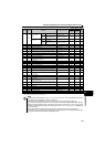
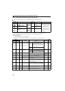
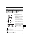
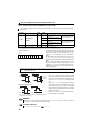
When using the RY, RY2 and RUN signals, assign functions to Pr.190 to Pr.192 (output terminal selection function) referring to
the table below.
Output
signal
Pr.190 to Pr.192 setting
Positive logic Negative logic
RY 11 111
RY2 33 133
RUN 0 100
REMARKS
The RUN signal (positive logic) is assigned to the terminal RUN in the initial setting.
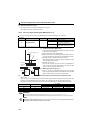
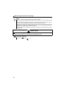
When the start command (STF, STR) is turned ON during PM motor control, the RUN signal is output after Pr.736
Electromagnetic brake interlock time plus about 100ms. This delay is caused by the electromagnetic brake interlock and magnetic
pole detection. (Refer to page 135)
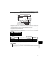
Time
Power supply
Rotation speed
STF
RH
RY
RY2
Zero speed control,
servo lock, or
DC injection brake
RUN
Reset
processing
Initial magnetic pole detection
(approx. 100ms)
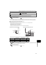
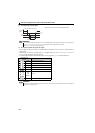
Drive unit
status
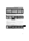
During stop
During
operation
LX signal ON
(pre-excitation)
Under zero speed control
or during DC injection
brake operation
(pre-excitation)
Output shutoff
Output signal
RY ON ON ON ON OFF
RY2 OFF
ON ON ON OFF
RUN OFF
ON OFF OFF OFF
There is a 100ms time delay at ON.
During a fault occurrence, while the MRS signal is ON, while the SON signal is OFF, etc.