


201
Communication operation and setting
4
PARAMETERS
4.18 Communication operation and setting
4.18.1 Wiring and configuration of PU connector
Using the PU connector, you can perform communication operation from a personal computer etc.
When the PU connector is connected with a personal, FA or other computer by a communication cable, a user program can
run and monitor the drive unit or read and write to parameters.
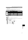
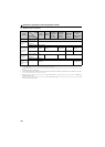
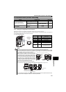
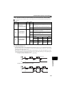
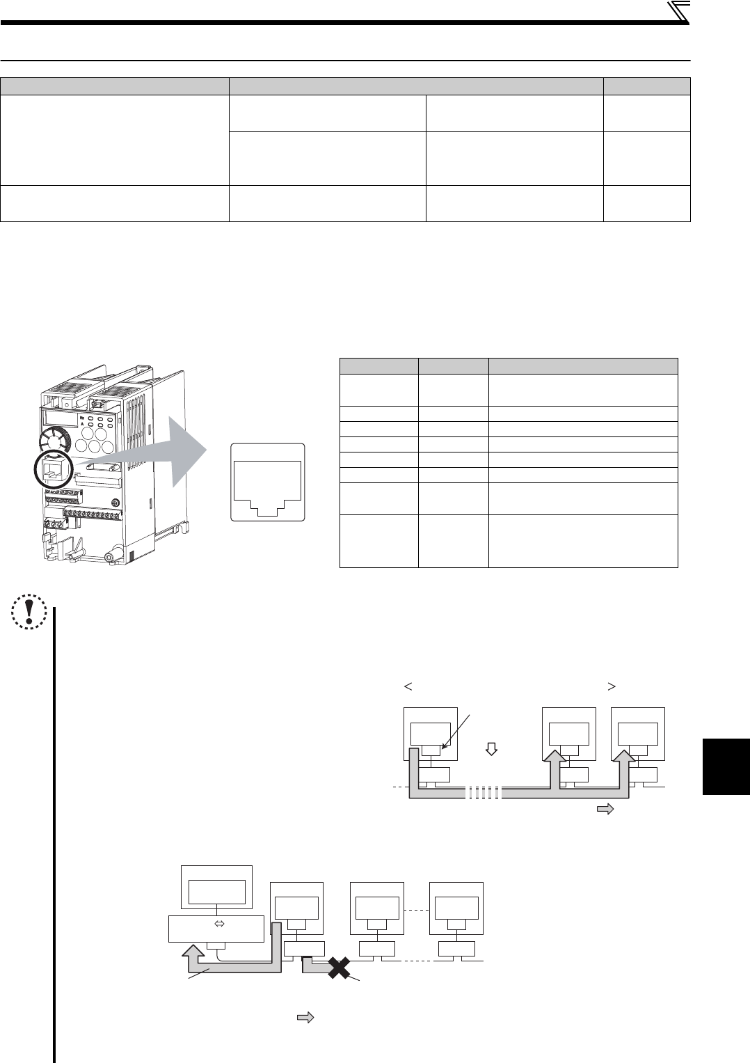
(1) PU connector pin-outs
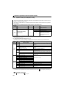
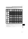
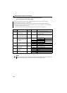
Purpose Parameter to set Refer to page
To perform communication
operation from PU connector
Initial setting of computer link
communication (PU connector)
Pr.117 to Pr.124
204
Modbus-RTU communication
specifications
Pr.117, Pr.118, Pr.120,
Pr.122, Pr.343, Pr.502,
Pr.549
222
To restrict parameter write through
communication
Communication EEPROM write
selection
Pr.342
208
Pin Number Name Description
1) SG
Earth (ground)
(connected to terminal 5)
2) Parameter unit power supply
3) RDA Drive unit receive+
4) SDB Drive unit send-
5) SDA Drive unit send+
6) RDB Drive unit receive-
7) SG
Earth (ground)
(connected to terminal 5)
8)
Earth (ground)
(connected to terminal 5)
NOTE
Pins No. 2 and 8 provide power to the parameter unit. Do not use these pins for RS-485 communication.
When making RS-485 communication with a combination of the FR-E700EX series, FR-E500 series, and FR-S500
series, incorrect connection of pins No.2 and 8 (parameter unit power supply) of the above PU connector may result
in a malfunction or failure of the inverter or drive unit.
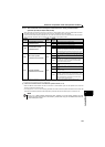
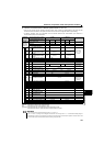
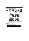
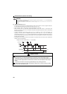
When multiple drive units are connected using pins No.2
and No.8, power is provided from the drive unit which is
powered ON to the drive units which are powered OFF in
case drive units which are powered ON and OFF are mixed.
In such a case, a protective circuit of the drive unit, which is
ON, functions to stop communication. When connecting
multiple drive units for RS-485 communication, make sure
to disconnect cables from No.2 and No.8 so that pins No.2
and No.8 are not connected between drive units.
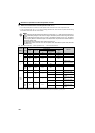
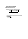
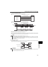
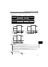
When using the RS-485 converter which receives power
from the drive unit, make sure that power is provided from one drive unit only. (Refer to the figure below.)
Do not connect the PU connector to the computer's LAN board, FAX modem socket or telephone modular connector.
The product could be damaged due to differences in electrical specifications.
1) to 8)
Drive unit
(receptacle side)
Front view
PU
connector
PU
connector
PU
connector
Drive unit Drive unit Drive unit
Protective
circuit
operation
(shut-off)
Communication
stop
ON OFF OFF
: Power supply
When pins No.2 and No.8 are connected
Computer
Terminating resisto
r
PU
connector
Drive unit
Connect pins No.2 and No.8
of one drive unit and a converter only.
Do not connect pins No.2 and No.8
of the other drive units.
Station 1 Station 2 Station n
RS-232C RS-485
converter
RS-232C
connector
Distributor
PU
connector
Drive unit
PU
connector
Drive unit
: Power supply