


299
6
PRECAUTIONS FOR MAINTENANCE AND INSPECTION
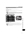
Measurement of main circuit voltages, currents and powers
6.2.7 Measurement of drive unit output frequency
A pulse train proportional to the output frequency is output across the frequency meter signal output terminal FM-SD of the
drive unit. This pulse train output can be counted by a frequency counter, or a meter (moving-coil type voltmeter) can be used
to read the mean value of the pulse train output voltage. When a meter is used to measure the output frequency,
approximately 5VDC is indicated at the maximum frequency.
For detailed specifications of the frequency meter signal output terminal FM, refer to page 162.
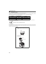
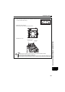
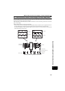
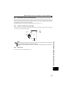
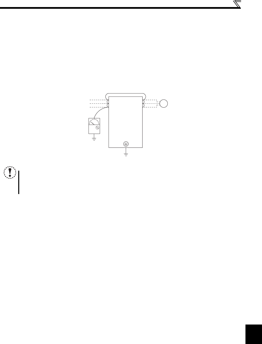
6.2.8 Insulation resistance test using megger
For the drive unit, conduct the insulation resistance test on the main circuit only as shown below and do not perform the test
on the control circuit. (Use a 500VDC megger.)
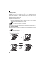
6.2.9 Pressure test
Do not conduct a pressure test. Deterioration may occur.
NOTE
Before performing the insulation resistance test on the external circuit, disconnect the cables from all terminals of
the drive unit so that the test voltage is not applied to the drive unit.
For the electric continuity test of the control circuit, use a tester (high resistance range) and do not use the megger or
buzzer.
U
V
W
Drive unit
Earth (Ground)
500VDC
megger
Power
supply
M
Moto
r
R/L1
S/L2
T/L3