


282
Check first when you have a trouble
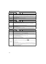
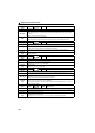
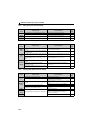
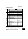
5.5.3 Motor generates heat abnormally
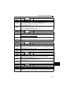
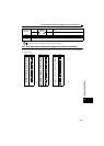
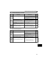
5.5.4 Motor rotates in the opposite direction
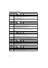
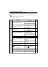
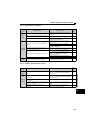
5.5.5 Speed greatly differs from the setting
Check
Points
Possible Cause Countermeasures
Refer
to
page
Motor
The required space is not provided around the motor. Improve the environment around the motor.
The mounting flange is small. Use a bigger flange.
Main
Circuit
The drive unit output voltage (U, V, W) are unbalanced.
Check the output voltage of the drive unit.
Check the insulation of the motor.
289
Motor current is large. Refer to "5.5.10 Motor current is too large" 284
Check
Points
Possible Cause Countermeasures
Refer
to
page
Main
Circuit
Phase sequence of output terminals U, V and W is
incorrect.
Connect phase sequence of the output cables (terminal
U, V, W) to the motor correctly
15
The rotation direction of the output shaft is changed by
the reduction gear.
Check the rotation direction of the motor's output shaft. 15
Input
Signal
The start signals (forward rotation, reverse rotation) are
connected improperly.
Check the wiring. (STF: forward rotation, STR: reverse
rotation)
18
Adjustment by the rotation speed is improper during the
reversible operation with Pr.73 Analog input selection
setting.
Check the setting of Pr.125, Pr.126, C2 to C7. 173
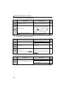
Parameter
Setting
Pr.40 RUN key rotation direction selection setting is
incorrect.
Check the Pr.40 setting. 255
Under position control, the sign of the position
command is incorrect.
Check the sign setting of positioning sub-function in
Pr.525 to Pr.531.
95
Under position control, the Pr.463 Position control rotation
direction selection setting is incorrect.
Check the Pr.463 setting. 92
Check
Points
Possible Cause Countermeasures
Refer
to
page
Input
Signal
Speed setting signal is incorrectly input. Measure the input signal level.
The input signal lines are affected by external EMI.
Take countermeasures against EMI such as using
shielded wires for input signal lines.
36
Parameter
Setting
Pr.1, Pr.2, calibration parameter C2 to C7 settings are
improper.
Check the settings of Pr.1 Maximum setting, Pr.2 Minimum
setting.
115
Check the calibration parameter C2 to C7 settings. 173
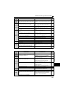
Pr.31 to Pr.36 (speed jump) settings are improper. Narrow down the range of speed jump. 116
Under position control, the maximum speed setting is
incorrect in Pr.4 to Pr.6, and Pr.24 to Pr.27.
Check the maximum speed setting in Pr.4 to Pr.6, and
Pr.24 to Pr.27.
95
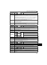
Load
Torque limit function is activated due to a heavy load.
Reduce the load weight.
Parameter
Setting
Set Pr.22 Torque limit level higher according to the load.
(Setting Pr.22 too large may result in frequent
overcurrent trip (E.OC).)
111
Motor
Check the capacities of the drive unit and the motor.