


296
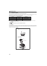
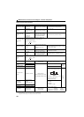
Measurement of main circuit voltages, currents and powers
Measuring Points and Instruments
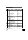
Item Measuring Point Measuring Instrument Remarks (Reference Measured Value)
Power supply voltage
V1
R/L1 and S/L2
S/L2 and T/L3
T/L3 and R/L1
Moving-iron type AC voltmeter
Commercial power supply
Within permissible AC voltage fluctuation
(Refer to page 302)
Power supply side
current
I1
R/L1, S/L2, T/L3 line
current
Moving-iron type AC ammeter
Power supply side
power
P1
R/L1, S/L2, T/L3 and
R/L1 and S/L2,
S/L2 and T/L3,
T/L3 and R/L1
Digital power meter (designed
for inverter) or electrodynamic
type singlephase wattmeter
P
1=W11+W12+W13 (3-wattmeter method)
Power supply side
power factor
Pf1
Calculate after measuring power supply voltage, power
supply side current and power supply side power.
[Three-phase power supply]
Output side voltage
V2
Across U and V,
V and W,
W and U
Rectifier type AC voltage meter
,
(moving-iron type cannot
measure)
Difference between the phases is within 1% of the
maximum output voltage.
Output side current
I2
U, V and W line currents
Approximate effective-value
rectifier type AC ammeter
Difference between the phases is 10% or lower of
the rated drive unit current.
Output side power
P2
U, V, W and
U and V,
V and W
Digital power meter (designed
for inverter) or electrodynamic
type singlephase wattmeter
P
2=W21+W22
2-wattmeter method (or 3-wattmeter method)
Output side power
factor
Pf2
Calculate in similar manner to power supply side power factor.
Converter output Across P/+ and N/-
Moving-coil type
(such as tester)
Drive unit LED display is lit. 1.35 V1
380V maximum during regeneration
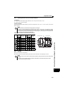
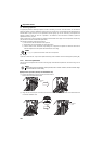
Frequency setting
signal
Across 2(+) and 5
Moving-coil type
(tester and such may be used)
(internal resistance 50k
or more)
DC0 to 10V, 4 to 20mA
"5" is
common
Across 4(+) and 5
Frequency setting
power supply
Across 10(+) and 5 DC5.2V
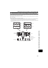
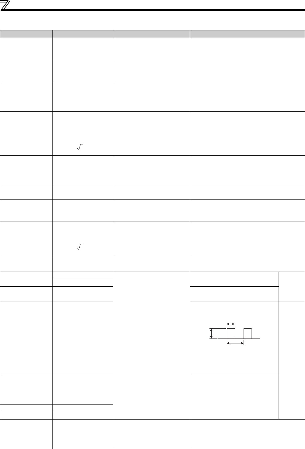
Frequency meter
signal
Across FM(+) and SD
Approximately 5VDC at maximum
frequency (without frequency meter)
Pulse width T1: Adjust with C0 (Pr.900)
Pulse cycle T2: Set with Pr.55
(frequency monitor only)
"SD" is
common.
Start signal
Select signal
Across SD and the
following:
STF, STR, RH, RM, or
RL(+)
When open
20 to 30VDC
ON voltage: 1V or less
Reset Across RES(+) and SD
Output stop Across MRS(+) and SD
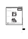
Fault signal
Across A and C
Across B and C
Moving-coil type
(such as tester)
Electric continuity check
<Normal> <Fault>
Across A and C Discontinuity Continuity
Across B and C Continuity Discontinuity
Use an FFT to measure the output voltage accurately. An FA tester or general measuring instrument cannot measure accurately.
When the setting of Pr.192 A,B,C terminal function selection is positive logic.
A digital power meter (designed for inverter) can also be used to measure.
Pf1
P1
3V1 I 1
------------------------
100=
%
Pf2
P2
3V2 I2
------------------------
100
%
DC8V
T1
T2