


306
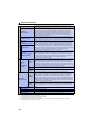
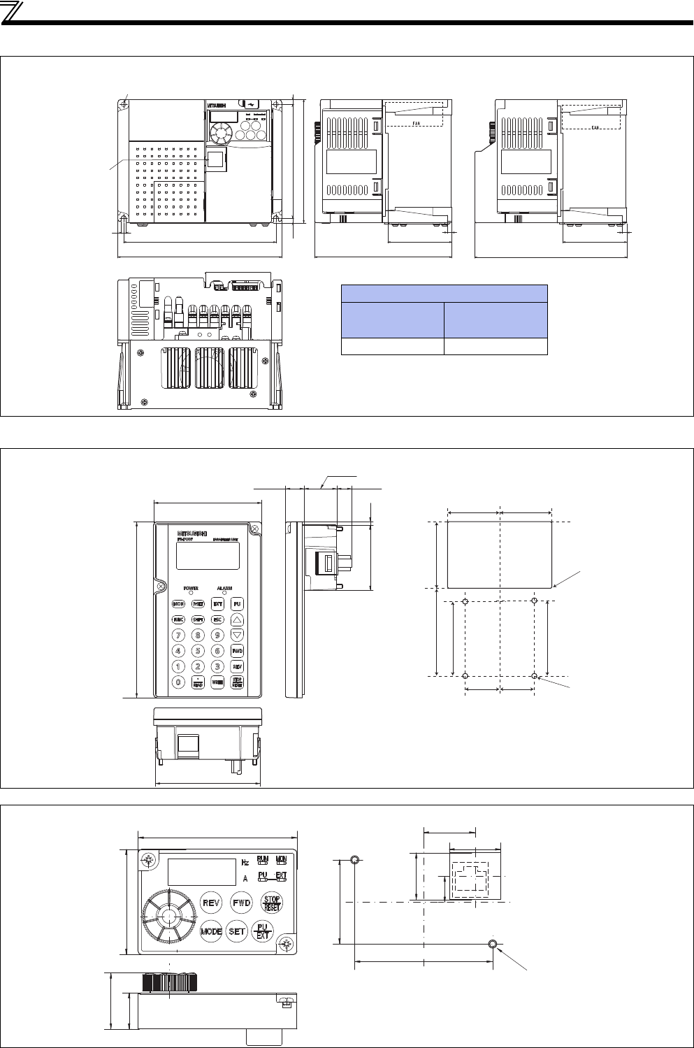
Outline dimension drawings
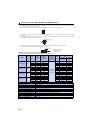
FR-E720EX-3.7K
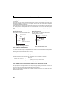
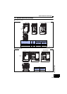
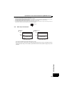
Parameter unit (option) (FR-PU07)
<Outline drawing> <Enclosure cut dimension drawing>
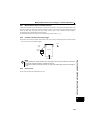
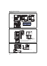
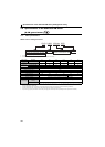
Enclosure surface operation panel (option) (FR-PA07)
<Outline drawing> <Enclosure cut dimension drawing>
5
158
170
5
118
5
128
5
142.5
D2
5
Rating
plate
Rating
plate
2-φ5 hole
Capacity
plate
66.5 66.5
When used with
the plug-in option
(Unit: mm)
D2
When used with
FR-A7NC E kit
When used with
FR-E7DS
159.6 170
80.3
(14.2)
2.5
50
(11.45)
25.05
135
83
∗1
∗1
∗1
∗1
∗2
67
51
40
56.8
57.8
26.5
4-R1
Air
bleeding
hole
4-φ4 hole
(Effective depth of the
installation screw hole 5.0)
M3 screw
26.5
40
When installing the FR-PU07 on the enclosure, etc., remove
screws or fix the screws to the FR-PU07 with M3 nuts.
Select the installation screw whose length will not exceed the
effective depth of the installation screw hole.
(Unit: mm)
68
45
59
36
22
22
11
20
(15.5)
24
2-M3 screw
(Unit: mm)